154
Startline S 424-S 421-S 521-S 524
Operator manual
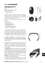
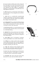
the area of contact with the ground, the casing and
the shim under the tread are reinforced with an
annular structure, usually called a belt. The tread
and sidewall work with different, independent
rigidities, so during rolling, sidewall flexure is not
transmitted to the tread.
4 - Side ring.
This is a metal ring comprising sev-
eral steel strands. The casing plies are secured to
the side ring.
5 - Belt
. This is a non-flexible circumferential
structure comprising cross-plies at very low angles,
positioned below the tread, with the aim to stabilise
the casing in the footprint area.
6 - Centring band
. This is a small mark that indicates
the circumference of the upper part of the bead
and is used as a reference to control correct tyre
centring on the rim after mounting.
7 - Protective band
. This is a circumferential marking
in the area of the sidewall which is more exposed
to accidental rubbing.
8 - Sidewall.
This is the area between the shoulder
and the centring band. It consists of a more or less
thin layer of rubber, which protects the casing plies
from lateral impact.
9 - Inner lining.
This is a vulcanised, compound
sheet, impermeable to air, inside tubeless tyres.
10 - Filling.
It is a rubber profile with a triangular
section, placed above the rim; it provides rigidity for
the bead and gradually offsets the abrupt uneven
thickness caused by the side ring.
11 - Flap
. This is the part of the casing ply around
the side ring and placed against the casing, to
secure the ply and prevent it from slipping.
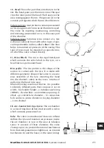
12 - Foot
. This is the innermost layer of the tread in
contact with the belt, or if the latter is not present
(conventional tyres) with the last casing ply.
13 - Shoulder.
This is the outer part of the tread,
between the corner and start of the sidewall.
7
14
6
11
2
10
4
a
c
d
e
b
Summary of Contents for Startline S 421
Page 64: ...64 Startline S 424 S 421 S 521 S 524 Manuale Operatore Montaggio...
Page 77: ...Startline S 424 S 421 S 521 S 524 Manuale Operatore 77 I 18 SCHEMA ELETTRICO GENERALE...
Page 78: ...78 Startline S 424 S 421 S 521 S 524 Manuale Operatore...
Page 79: ...Startline S 424 S 421 S 521 S 524 Manuale Operatore 79 I...
Page 81: ...Startline S 424 S 421 S 521 S 524 Manuale Operatore 81 I Note...
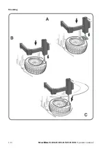
Page 144: ...144 Startline S 424 S 421 S 521 S 524 Operator manual Mounting...
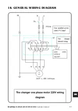
Page 157: ...Startline S 424 S 421 S 521 S 524 Operator manual 157 UK 18 GENERAL WIRING DIAGRAM...
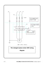
Page 158: ...158 Startline S 424 S 421 S 521 S 524 Operator manual...
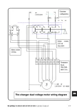
Page 159: ...Startline S 424 S 421 S 521 S 524 Operator manual 159 UK...
Page 161: ...Startline S 424 S 421 S 521 S 524 Operator manual 161 UK Notes...
Page 224: ...224 Startline S 424 S 421 S 521 S 524 Manuel Op rateur Montage...
Page 237: ...Startline S 424 S 421 321 S 524 Manuel Op rateur 237 F 18 SCH MA LECTRIQUE G N RAL...
Page 238: ...238 Startline S 424 S 421 S 521 S 524 Manuel Op rateur...
Page 239: ...Startline S 424 S 421 321 S 524 Manuel Op rateur 239 F...
Page 241: ...Startline S 424 S 421 321 S 524 Manuel Op rateur 241 F Notes...
Page 304: ...304 Startline S 424 S 421 S 521 S 524 Bedienungsanleitung Montage...
Page 317: ...Startline S 424 S 421 S 521 S 524 Bedienungsanleitung 317 D 17 ALLGEMEINGER SCHALTPLAN...
Page 318: ...318 Startline S 424 S 421 S 521 S 524 Bedienungsanleitung...
Page 319: ...Startline S 424 S 421 S 521 S 524 Bedienungsanleitung 319 D...
Page 321: ...Startline S 424 S 421 S 521 S 524 Bedienungsanleitung 321 D Anmerkungen...
Page 384: ...384 Startline S 424 S 421 S 521 S 524 Manual Operador Montaje...
Page 397: ...Startline S 424 S 421 S 521 S 524 Manual Operador 397 E 18 ESQUEMA EL CTRICO GENERAL...
Page 398: ...398 Startline S 424 S 421 S 521 S 524 Manual Operador...
Page 399: ...Startline S 424 S 421 S 521 S 524 Manual Operador 399 E...
Page 401: ...Startline S 424 S 421 S 521 S 524 Manual Operador 401 E Notas...

