124
Startline S 424-S 421-S 521-S 524
Operator manual
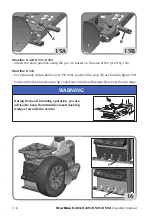
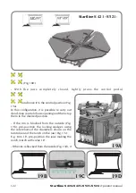
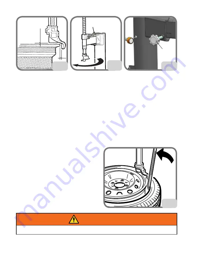
The space between the rim and the tool head will be maintained for as long as the handle
is in the locking position. The operator can tilt the pole freely (e.g. when demounting
wheels of the same size) without repositioning the tool head.
9.5.b TOOL HEAD POSITIONING (Startline S 424 - Startline S 421)
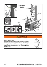
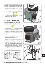
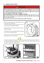
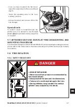
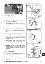
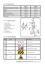
- Take the horizontal arm into the operating position (Fig. 24)
- Lower the vertical arm until the tool head touches the upper rim edge.
- Adjust the opening of the horizontal arm using the handwheel (B, Fig. 24A) to create
the distance of about 2 mm between the tool head and the rim (B, Fig. 23A)
- Lock the vertical arm using the lever (A,
Fig. 24).
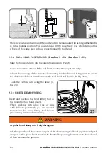
9.5.c WHEEL DEMOUNTING
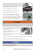
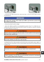
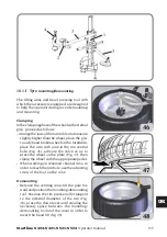
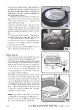
-Insert and position the bead lifting tool on
the mounting tool head (fig.25).
When working with alloy rims or rims
with delicate paintwork, you are advised
to remove the bead lifting tool before
proceeding with the demounting.
Grip the bead lifting tool firmly during use.
WARNING
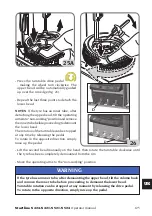
- Lift the upper bead above the rear part of the demounting tool head (fig.25A) and push
one part of the upper bead into the rim channel by pushing downwards on the side wall
of the tyre near the operator.
B
A
23A
25
24
A
A
B
24A
Summary of Contents for Startline S 421
Page 64: ...64 Startline S 424 S 421 S 521 S 524 Manuale Operatore Montaggio...
Page 77: ...Startline S 424 S 421 S 521 S 524 Manuale Operatore 77 I 18 SCHEMA ELETTRICO GENERALE...
Page 78: ...78 Startline S 424 S 421 S 521 S 524 Manuale Operatore...
Page 79: ...Startline S 424 S 421 S 521 S 524 Manuale Operatore 79 I...
Page 81: ...Startline S 424 S 421 S 521 S 524 Manuale Operatore 81 I Note...
Page 144: ...144 Startline S 424 S 421 S 521 S 524 Operator manual Mounting...
Page 157: ...Startline S 424 S 421 S 521 S 524 Operator manual 157 UK 18 GENERAL WIRING DIAGRAM...
Page 158: ...158 Startline S 424 S 421 S 521 S 524 Operator manual...
Page 159: ...Startline S 424 S 421 S 521 S 524 Operator manual 159 UK...
Page 161: ...Startline S 424 S 421 S 521 S 524 Operator manual 161 UK Notes...
Page 224: ...224 Startline S 424 S 421 S 521 S 524 Manuel Op rateur Montage...
Page 237: ...Startline S 424 S 421 321 S 524 Manuel Op rateur 237 F 18 SCH MA LECTRIQUE G N RAL...
Page 238: ...238 Startline S 424 S 421 S 521 S 524 Manuel Op rateur...
Page 239: ...Startline S 424 S 421 321 S 524 Manuel Op rateur 239 F...
Page 241: ...Startline S 424 S 421 321 S 524 Manuel Op rateur 241 F Notes...
Page 304: ...304 Startline S 424 S 421 S 521 S 524 Bedienungsanleitung Montage...
Page 317: ...Startline S 424 S 421 S 521 S 524 Bedienungsanleitung 317 D 17 ALLGEMEINGER SCHALTPLAN...
Page 318: ...318 Startline S 424 S 421 S 521 S 524 Bedienungsanleitung...
Page 319: ...Startline S 424 S 421 S 521 S 524 Bedienungsanleitung 319 D...
Page 321: ...Startline S 424 S 421 S 521 S 524 Bedienungsanleitung 321 D Anmerkungen...
Page 384: ...384 Startline S 424 S 421 S 521 S 524 Manual Operador Montaje...
Page 397: ...Startline S 424 S 421 S 521 S 524 Manual Operador 397 E 18 ESQUEMA EL CTRICO GENERAL...
Page 398: ...398 Startline S 424 S 421 S 521 S 524 Manual Operador...
Page 399: ...Startline S 424 S 421 S 521 S 524 Manual Operador 399 E...
Page 401: ...Startline S 424 S 421 S 521 S 524 Manual Operador 401 E Notas...

