130
Startline S 424-S 421-S 521-S 524
Operator manual
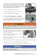
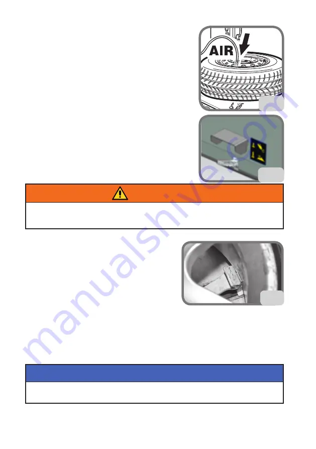
- Inflate the tyre with the appropriate gun or by pressing
the pedal in an intermediate position (Fig. 34). Frequently
check the pressure on the pressure gauge to make sure
that the pressure NEVER exceeds the maximum pressure
indicated by the manufacturer on the tyre.
- Disconnect inflation hose from valve rod.
- Take the operating arms to the “non -” position.
- Remove the wheel from the tyre changer.
9.8.c. SPECIAL PROCEDURE (TI VERSION)
The TI version facilitates bead insertion and inflation of
Tubeless tyres through the emission of a strong jet of air
from the nozzles placed near the locking wedges.
Before starting with the operations described below, make sure there is no dirt, dust
or other impurities near the inflation nozzles. It is advisable to wear protective goggles.
WARNING
- Verify that both upper and lower tyre beads and
rim bead seat have been properly lubricated with an
approved mounting paste.
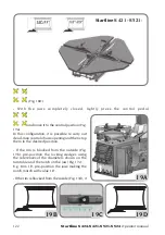
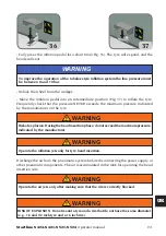
- Move the horizontal arm to the wheel centre (all
slipped off towards the operator)
- Make sure that the wheel is clamped to the turntable
from the inner side (fig.35).
- Lower the vertical arm until it touches the rim (fig.31), then clamp the arm in this position.
- Remove the valve core if it has not already been removed (Fig. 32).
- Connect the Doyfe connector of the inflating hose to the valve stem (Fig. 33).
To increase the effectiveness of the air jets, manually lubricate and lift the lower
bead before activating the nozzles.
WARNING
33
34
35
Summary of Contents for Startline S 421
Page 64: ...64 Startline S 424 S 421 S 521 S 524 Manuale Operatore Montaggio...
Page 77: ...Startline S 424 S 421 S 521 S 524 Manuale Operatore 77 I 18 SCHEMA ELETTRICO GENERALE...
Page 78: ...78 Startline S 424 S 421 S 521 S 524 Manuale Operatore...
Page 79: ...Startline S 424 S 421 S 521 S 524 Manuale Operatore 79 I...
Page 81: ...Startline S 424 S 421 S 521 S 524 Manuale Operatore 81 I Note...
Page 144: ...144 Startline S 424 S 421 S 521 S 524 Operator manual Mounting...
Page 157: ...Startline S 424 S 421 S 521 S 524 Operator manual 157 UK 18 GENERAL WIRING DIAGRAM...
Page 158: ...158 Startline S 424 S 421 S 521 S 524 Operator manual...
Page 159: ...Startline S 424 S 421 S 521 S 524 Operator manual 159 UK...
Page 161: ...Startline S 424 S 421 S 521 S 524 Operator manual 161 UK Notes...
Page 224: ...224 Startline S 424 S 421 S 521 S 524 Manuel Op rateur Montage...
Page 237: ...Startline S 424 S 421 321 S 524 Manuel Op rateur 237 F 18 SCH MA LECTRIQUE G N RAL...
Page 238: ...238 Startline S 424 S 421 S 521 S 524 Manuel Op rateur...
Page 239: ...Startline S 424 S 421 321 S 524 Manuel Op rateur 239 F...
Page 241: ...Startline S 424 S 421 321 S 524 Manuel Op rateur 241 F Notes...
Page 304: ...304 Startline S 424 S 421 S 521 S 524 Bedienungsanleitung Montage...
Page 317: ...Startline S 424 S 421 S 521 S 524 Bedienungsanleitung 317 D 17 ALLGEMEINGER SCHALTPLAN...
Page 318: ...318 Startline S 424 S 421 S 521 S 524 Bedienungsanleitung...
Page 319: ...Startline S 424 S 421 S 521 S 524 Bedienungsanleitung 319 D...
Page 321: ...Startline S 424 S 421 S 521 S 524 Bedienungsanleitung 321 D Anmerkungen...
Page 384: ...384 Startline S 424 S 421 S 521 S 524 Manual Operador Montaje...
Page 397: ...Startline S 424 S 421 S 521 S 524 Manual Operador 397 E 18 ESQUEMA EL CTRICO GENERAL...
Page 398: ...398 Startline S 424 S 421 S 521 S 524 Manual Operador...
Page 399: ...Startline S 424 S 421 S 521 S 524 Manual Operador 399 E...
Page 401: ...Startline S 424 S 421 S 521 S 524 Manual Operador 401 E Notas...

