


5.4 Examples
35
The
DLC
control voltage is 0 to 2.5 V, corresponding to laser frequency
change of around 20 GHz (0.04 nm). If the frequency change is positive
for positive change in control voltage, a negative gain should be used for
negative feedback control. It would then seem logical to use an overall
gain of
−
2
.
5
/
0
.
04 =
−
62
.
5 V
/
nm, with each
DAC
output step (2.4 mV) cor-
responding to 0
.
0024
/
62
.
5 = 0
.
04 pm or approximately 20 MHz. With that
gain value
G
=
−
62
.
5 and
k
p
= 1, the system would have unity feedback
gain at all frequencies, which would be unstable. The proportional gain
should be much lower, either by reducing
k
p
<<
1 and/or by reducing
G
.
Start with
k
p
= 0 and use integration (e.g.
k
i
= 1) to achieve high gain at
low frequencies.
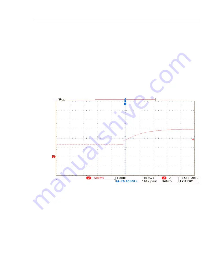
Figure 5.3:
MWM
output signal when
PID
is enabled for laser wavelength stabil-
isation. The setpoint wavelength was changed by 0.004 nm (about 2 GHz) causing
a rapid change in the control signal, which then integrates more slowly until the
new setpoint was reached. Gain
−
200 V/nm,
k
p
= 0,
k
i
= 1
.
0,
k
d
= 0.
The
SPAN
control on the
DLC
provides an adjustment of the overall gain,
which can be used to maximise the effective resolution. For example, if
the expected drift in the laser will be much less than the 0 to 2.5 V swing
Summary of Contents for MWM
Page 1: ...MWM wavemeter Revision 3 19 mogwave 1 4 15 Firmware 0 6 9 ...
Page 4: ...ii ...
Page 7: ...Contents v G Ugrading firmware 83 References 84 ...
Page 8: ...vi Contents ...
Page 54: ...46 Chapter 6 Calibration ...
Page 58: ...50 Appendix A Specifications ...
Page 66: ...58 Appendix B Communications ...
Page 70: ...62 Appendix C Programming ...
Page 86: ...78 Appendix E mogwave configuration ...
Page 92: ......
Page 94: ...86 ...
Page 95: ......