Mitsubishi Apricot FT2200 System Manual Download Page 51

System Configuration

3-11

3.1.5

Installing a Hot-swappable SCSI Drive

The system supports hot-swappable drive trays with wide SCSI or
narrow SCSI interface board.  The installation steps for the wide and
narrow SCSI drives are basically the same except for connecting the
wide SCSI drive ID cable.

If your system does not come with a
backplane board, proceed first to section 3.4
for instructions on installing the board.

Follow these steps to install a hot-swap SCSI drive:

1.

Open the lower front door.  Unlock the left panel security if it is
locked.

2.

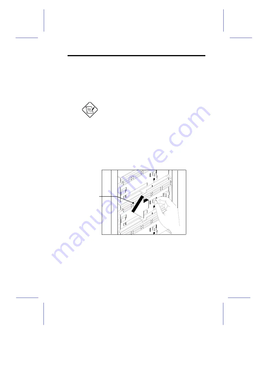
Push the drive tray switch to the Unlock/Power Off position.

Figure 3-11

Unlocking the Drive Tray Switch

Unlock/Power Off

Summary of Contents for Apricot FT2200

Page 1: ...FT2200 NATIONAL ACCREDITATION OFCERTIFICATION BODIES System Guide...

Page 2: ...FT2200 System Guide...

Page 3: ...ricot Computers Limited The software described in this manual is furnished under a license agreement The software may be used or copied only in accordance with the terms of this agreement It is agains...

Page 4: ...rheating these openings must not be blocked or covered The openings should never be blocked by placing the product on a bed sofa rug or other similar surface This product should never be placed near o...

Page 5: ...ening or removing covers may expose you to dangerous voltage points or other risks Refer all servicing to qualified service personnel 13 Unplug this product from the wall outlet and refer servicing to...

Page 6: ...tute a power cord from any other equipment To prevent fire and electric shock do not expose any part of the computer to rain or moisture and turn off the computer and unplug all power cords before mov...

Page 7: ...em 20 All interconnecting cables e g Microphone headphone and speaker and communication cables should be less than 2 metres in length If cable extensions are used ensure adequate earth connections are...

Page 8: ...earthed The power supplies in the computer and the monitor are correct for the country in which the system is first sold Do not alter any switch settings on the rear of the system If you wish to use t...

Page 9: ...e monitor at the same time 23 Power Cable Connections UK ONLY This equipment is supplied with an AC power lead that has a non removable moulded plug Always replace the fuse with one of the same type a...

Page 10: ...he system Chapter 2 Setting Up the System This chapter helps you get started It illustrates how to prepare the system for installation connect the cables and startup the system Chapter 3 System Config...

Page 11: ...the keyboard NOTE Gives bits and pieces of additional information related to the current topic WARNING Alerts you to any damage that might result from doing or not doing specific actions CAUTION Gives...

Page 12: ...anel 1 8 Chapter 2 Setting Up the System 2 1 Pre installation Requirements 2 1 2 1 1 Selecting a Site 2 1 2 1 2 Checking the Package Contents 2 2 2 1 3 Transporting the System 2 3 2 1 4 Positioning th...

Page 13: ...1 Layout 3 18 3 2 2 Jumpers and Connectors 3 19 3 2 3 Installing a Pentium Pro CPU 3 24 3 3 Memory Board 3 26 3 3 1 Layout 3 26 3 3 2 Rules for Adding Memory 3 26 3 3 3 Memory Configurations 3 27 3 3...

Page 14: ...4 2 8 Enhanced IDE Features 4 9 4 2 9 Num Lock After Boot 4 9 4 2 10 Memory Test 4 10 4 2 11 Auto Configuration Mode 4 10 4 2 12 Fast Boot Mode 4 10 4 3 Advanced System Configuration 4 11 4 3 1 Shado...

Page 15: ...al Memory Region 4 25 4 7 Load Setup Default Settings 4 26 4 8 Leaving Setup 4 27 Chapter 5 Diagnostics and Utilities 5 1 EISA Configuration Utility v3 0 5 1 5 1 1 Functions 5 1 5 1 2 Making Menu Sele...

Page 16: ...rd 2 6 2 5 Connecting a Mouse 2 7 2 6 Connecting a VGA Monitor 2 8 2 7 Connecting a Printer 2 9 2 8 Power Cables 2 10 2 9 Opening the Upper Front Panel 2 11 2 10 System Power On 2 12 3 1 System Housin...

Page 17: ...15 3 17 Removing a Bracket Cover 3 16 3 18 Installing an Expansion Board 3 17 3 19 System Board Layout 3 18 3 20 Jumper and Connector Locations 3 19 3 21 VRM Settings for CPU1 3 3V for 200 MHz 3 21 3...

Page 18: ...ort 5 7 5 6 Save and Exit 5 9 5 7 Add or Remove Boards 5 11 5 8 View or Edit Details 5 13 List of Tables 1 1 LED Indicator Description 1 7 3 1 Jumper Settings 3 20 3 2 Voltage Identification Codes 3 2...

Page 19: ...xviii...

Page 20: ...oller the Pentium Pro running at up to 200 MHz carries a new generation of power not present in its predecessors The system board has two CPU sockets to accommodate up to two Intel Pentium Pro CPUs fo...

Page 21: ...I O APIC unit facilitate multiprocessor interrupt management The APIC works with multiple I O subsystems where each subsystem have its own interrupts that help minimize centralized system overhead Bus...

Page 22: ...2 System Architecture The system bus PCI buses EISA bus Orion PCI bridge OPB Orion memory controller OMC PCI EISA Bridge PCEB and EISA system controller ESC comprise the basic system architecture Fig...

Page 23: ...orts a number of features that ensure high reliability It has an 8 bit error correction code ECC that protects the data lines and a 2 bit parity code that protects the address lines The bus uses the g...

Page 24: ...between the system bus and the system memory It consists of the DRAM control DC chip and the data path DP chip The OMC relates to the DRAM array through four memory interface controller MIC chips The...

Page 25: ...ors and an embedded reset switch The lower part contains the externally accessible hard disk drive bays with eight drive trays for narrow or wide SCSI disk drives The basic system may only have a 3 5...

Page 26: ...er Switch The power switch allows you to turn the system power on or off Keylock The system housing comes with mechanical security lock on the left panel preventing unauthorized access to the internal...

Page 27: ...nter and serial devices Beside the connectors are the monitor and power sockets On the lower section are the slot openings for expansion boards Figure 1 4 Rear Panel Power Supply Power Socket COM1 COM...

Page 28: ...Selecting a Site Before unpacking and installing the system select a suitable site for the system for maximum efficiency The system is suitable to set up in an office environment Consider the followi...

Page 29: ...owing items from the package System Unit System Guide EISA Configuration Utility VGA Manual and Driver Kit SCSI Manuals and Driver Kit If any of the above items is damaged or missing contact your deal...

Page 30: ...n top and two wheels behind the feet to facilitate moving to short distances When transporting the system pull out the handle at the same time lifting the unit front a few inches from the ground Slide...

Page 31: ...you begin setting up the system position the system unit either as a standalone or against a wall so it is stable when you connect the cables For a standalone system rotate the feet outward as in Figu...

Page 32: ...nding the system with the fan facing a wall leave a space of 5 10 cm from the wall to allow air circulation then position the feet as in Figure A When standing the system with the fan facing out you c...

Page 33: ...unit keyboard mouse and monitor constitute the basic system Before connecting any other peripherals connect these peripherals first then apply power to test the basic system if it is running properly...

Page 34: ...Setting Up the System 2 7 2 2 2 Mouse Figure 2 5 Connecting a Mouse...

Page 35: ...2 8 System Guide 2 2 3 VGA Monitor Figure 2 6 Connecting a VGA Monitor...

Page 36: ...2 2 4 Printer Should you need to connect a printer to the system in the future attach the printer cable to the parallel port on the rear panel as in Figure 2 7 Connecting a printer is optional Figure...

Page 37: ...2 10 System Guide 2 2 5 Power Cables Figure 2 8 Power Cables...

Page 38: ...t up the system properly and connected all the required cables you may now apply power to the system 2 3 1 Turning On the System Power The power switch is inside the upper front panel Hold the right e...

Page 39: ...m Power On If the system does not turn on or boot after pressing the power switch go to the next section for the possible causes of the boot failure You can determine if the system is in good conditio...

Page 40: ...the power source to the power socket on the rear panel Make sure that the cable is properly connected No power comes from the grounded power outlet Have an electrician check your power outlet if it is...

Page 41: ...jor components housing system board memory board SCSI disk array backplane board and power supply This chapter discusses the system hardware configuration in detail 3 1 System Housing The system housi...

Page 42: ...expansion boards The upper front section accommodates a 3 5 inch and three 5 25 inch drives while the lower section holds the eight hot swappable SCSI drive trays These devices on the front section a...

Page 43: ...the internal components The lock also protects the SCSI disk array hard disks You cannot open the lower front panel unless you open the left panel security lock When installing components unlock and r...

Page 44: ...t Panel Follow these steps to open the left panel 1 Unlock the left panel security with the system key The system key is attached on the inner side of the upper front panel Figure 3 4 Opening the Lowe...

Page 45: ...System Configuration 3 5 Left Panel Pull on the key to swing the left panel open If necessary you may use a screwdriver to pry open the panel Figure 3 5 Opening the Left Panel...

Page 46: ...s in the following sections unless you are confident of your capability to perform them Otherwise ask a service technician for assistance 3 1 4 Installing External Devices The housing supports one 3 5...

Page 47: ...install a 3 5 inch diskette drive 1 Open the lower front panel Unlock the left panel security if it is locked 2 Remove the upper front panel including its frame by pressing the latch underside and pul...

Page 48: ...y installed drive remove the old drive from the frame 4 Secure a 3 5 inch drive on the frame with four screws Figure 3 7 Attaching a 3 5 inch Diskette Drive on the Frame 5 Insert the drive into the dr...

Page 49: ...ame by pressing the latch underside and pulling the panel and frame out See Figure 3 6 3 Attach the metal guides on the sides of the external device such as a CD ROM drive that you wish to install Fig...

Page 50: ...System Configuration 3 10 4 Insert the drive into the bay Figure 3 10 Installing a 5 25 inch External Device 5 Connect the drive power and signal cables...

Page 51: ...y the same except for connecting the wide SCSI drive ID cable If your system does not come with a backplane board proceed first to section 3 4 for instructions on installing the board Follow these ste...

Page 52: ...rd ID setting feature allows you to set the wide SCSI device IDs on the backplane board Make sure that you have set jumpers J3 and J4 on the backplane board for additional SCSI IDs See section 3 4 4 f...

Page 53: ...wide SCSI only and power cable Make sure that all cables are properly and completely connected Figure 3 13 Connecting the Drive Cables Wide SCSI Drive Figure 3 14 Connecting the Drive Cables Narrow SC...

Page 54: ...tray handle into place Make sure to push the drive tray handle back after inserting the tray into the bay Otherwise the tray does not fit in completely 8 Push back the drive into the bay until it fits...

Page 55: ...System Configuration 3 15 9 Push the drive tray switch to the Lock Power On position Figure 3 16 Locking the Drive Tray Switch Lock Power On...

Page 56: ...Expansion Board Follow these steps to install an expansion board 1 Unlock the security lock and open the left panel 2 Remove the bracket cover opposite an empty PCI or EISA slot Save the screw for la...

Page 57: ...rt the golden finger connector until it fits in completely 4 Secure the board with a screw Figure 3 18 Installing an Expansion Board If you installed an EISA board run the EISA configuration utility E...

Page 58: ...nnector 4 VRM connector 1 5 Memory board slot 6 Pentium Pro CPU socket 1 7 Fan5 8 VGA RAM 9 Fan1 10 Fan2 11 Fan3 12 Buzzer 13 Real time clock 14 RDM cable connector 15 BIOS 16 Narrow SCSI interface 17...

Page 59: ...nfiguration 3 19 3 2 2 Jumpers and Connectors Figure 3 20 shows the jumper and connector locations on the system board Figure 3 20 Jumper and Connector Locations The blackened pin of a jumper represen...

Page 60: ...15 are for CPU testing purposes only Note Do not reconfigure SCSI Termination J16 1 2 2 3 SCSI terminator set to On SCSI terminator switchable to On or Off using the SCSI Setup Utility Password Securi...

Page 61: ...or J1 to 3 3V at 200 MHz Figure 3 21 VRM Settings for CPU1 3 3V for 200 MHz Figure 3 22 shows the settings of jumpers J7 J8 J9 and J10 to set CPU2 VRM connector J6 to 3 3V at 200 MHz Figure 3 22 VRM S...

Page 62: ...1 1 0 0 2 3 1 0 1 1 2 4 1 0 1 0 2 5 1 0 0 1 2 6 1 0 0 0 2 7 0 1 1 1 2 8 0 1 1 0 2 9 0 1 0 1 3 0 0 1 0 0 3 1 0 0 1 1 3 2 0 0 1 0 3 3 0 0 0 1 3 4 0 0 0 0 3 5 0 Processor pin connected to Vss 1 Open DO...

Page 63: ...ette drive connector CN11 PS 2 keyboard mouse connector CN12 IDE hard disk connector CN13 Serial port connector CN14 Parallel port VGA port connector CN16 Hard disk LED connector CN17 Reset RDM cable...

Page 64: ...configuration Follow these steps to install a CPU 1 Release the heat sink locks 2 Attach the heat sink by sliding its rails along the longer sides of the rectangular Pentium Pro CPU Make sure that th...

Page 65: ...ly insert the CPU pins into the socket matching the denser pins with the denser holes on the socket Be careful not to bend any pins 6 Push down the socket lever 7 Connect the CPU fan cable to connecto...

Page 66: ...26 Memory Board Layout 3 3 2 Rules for Adding Memory Adhere to the following rules when you add system memory Always install SIMMs from bank 0 You should use the memory banks consecutively Always inst...

Page 67: ...8MB 2 8MB 2 8MB 2 8MB 2 8MB 2 128 MB 16MB 2 32 MB 16MB 2 16MB 2 64 MB 16MB 2 16MB 2 16MB 2 16MB 2 128 MB 16MB 2 16MB 2 16MB 2 16MB 2 16MB 2 16MB 2 16MB 2 16MB 2 256 MB 32MB 2 64 MB 32MB 2 32MB 2 128 M...

Page 68: ...SIMM fits only in one direction If you slip in a SIMM but does not completely fit you may have inserted it the wrong way Reverse the orientation of the SIMM 2 Gently push the SIMM to a vertical posit...

Page 69: ...moving a SIMM Follow these steps to remove a SIMM 1 Press the holding clips on both sides of the SIMM outward to release it 2 Move the SIMM to a 45 angle 3 Pull the SIMM out of the socket Figure 3 28...

Page 70: ...ow these steps to install the memory board 1 Align the memory board with the memory board slot on the system board Install the memory board with the component side up 2 Insert the board into the slot...

Page 71: ...acket behind the disk drives 4 Align the clamp rail with the board edge 5 Insert the other end of the clamp into the hole on the rear panel bracket Make sure to install the holding clamp properly It p...

Page 72: ...se steps to reconfigure the system 1 Turn the system on A memory error message appears indicating that the total memory does not match the value stored in CMOS 2 Press to enter Setup A warning message...

Page 73: ...major features Hot swap feature that allows replacement of a defective hard drive even while the system is in full operation This feature requires a RAID controller board and RAID drivers Supports wid...

Page 74: ...Figure 3 31 SCSI Disk Array Backplane Board Power Connectors SCSI Channel 1 SCSI Channel 2 SCSI Channel Out Channel Configuration Switches SCSI Drive Slot Terminators RA4 RA5 RA6 Terminators RA1 RA2...

Page 75: ...3 and 4 on the backplane J4 supports the four lower drive slots slots 5 6 7 and 8 See section 3 4 4 for details on hard disk ID settings Figure 3 32 shows the settings for jumpers J3 and J4 Note that...

Page 76: ...etting 3 pins on jumpers J3 and J4 allow you to set eight additional SCSI drive IDs for the SCSI devices installed in the system Table 3 5 shows the SCSI ID switch settings and the corresponding drive...

Page 77: ...el configuration channel 1 supports the SCSI devices plugged into slots 1 to 8 Set the channel configuration switches to Combine Note that terminators RA1 to 6 are always installed See Figure 3 31 for...

Page 78: ...in slots 5 to 8 Set the channel configuration switches to Split Note that terminators RA1 to 6 are always installed See Figure 3 31 for the locations of the switches and terminators Figure 3 34 Dual C...

Page 79: ......

Page 80: ......

Page 81: ...iguration values into the battery backed nonvolatile memory called CMOS RAM This memory area is not part of the system RAM If you repeatedly receive Run Setup messages the battery may be bad In this c...

Page 82: ...stem Configuration Advanced System Configuration System Security PCI System Configuration Non PnP ISA Card Configuration Remote Diagnostic Configuration Load Setup Default Settings Move Highlight Bar...

Page 83: ...x xx xx Base Memory xxx KB Extended Memory xxxx KB Total Memory xxxx KB Math Coprocessor Installed Video Display VGA EGA Move Highlight Bar Change Setting PgDn PgUp Move Screen Esc Exit The command li...

Page 84: ...hlight Bar Change Setting PgDn PgUp Move Screen Esc Exit The following sections explain the different parameters and their settings 4 2 1 Date and Time The real time clock keeps the system date and ti...

Page 85: ...inute 00 to 59 Second 00 to 59 4 2 2 Diskette Drives To enter the configuration value for the first diskette drive drive A highlight the Diskette Drive A parameter Press or key to view the options and...

Page 86: ...ting and self initialization before loading the operating system and applications the BIOS utility automatically determines your hard disk type You can see the drive type and its values when you enter...

Page 87: ...ighlight an hard disk parameter 2 Select the option User and press 3 Type in the number of cylinders heads and sectors of the drive under the appropriate columns Be sure to have the correct hard disk...

Page 88: ...olumns x 25 rows CGA 80 columns x 25 rows VGA EGA 4 2 7 Communication Settings The Communication Settings parameters allow you to set the baud rate parity stop bit and data length for the first serial...

Page 89: ...504 MB capacity that was previously configured through LBA mode If you use a hard disk configured through cylinder head sector CHS mode set this item to Disabled Hard Disk Block Mode This function en...

Page 90: ...ration Mode When enabled this parameter automatically sets the system configuration values to their optimized settings At the same time it causes the Memory Test parameter to be fixed to Disabled and...

Page 91: ...ion parameters Advanced System Configuration Page 1 1 Shadow RAM E0000h FFFFFh System BIOS Enabled C0000h C7FFFh Video BIOS Enabled C8000h CBFFFh Disabled CC000h CFFFFh Disabled D0000h D3FFFh Disabled...

Page 92: ...his item is fixed to Enabled The remaining address ranges are for I O ROM functions 4 3 2 L1 and L2 Cache CPU Cache This parameter enables or disables the first level and second level cache integrated...

Page 93: ...ull the CPU eventually writes the data to the memory address A0000h BFFFFh reserved for video data Setting to Non cacheable disables this feature 4 3 3 Memory at 15MB 16MB To prevent memory address co...

Page 94: ...Parallel Port Base Address 378h IRQ 7 Operation Mode Standard Parallel Port SPP Mode ECP DMA Channel Onboard PS 2 Mouse IRQ12 Enabled Setup Password None Power On Password None Move Highlight Bar Cha...

Page 95: ...all diskette functions Hard Disk Drive Setting Description Normal Hard disk drive functions normally Write Protect All Sectors Disables the write function on all sectors Write Protect Boot Sector Dis...

Page 96: ...8h Serial port 1 with address 3E8h using IRQ4 2E8h Serial port 1 with address 2E8h using IRQ3 Disabled Disables serial port 1 Serial Port 2 Base Address This parameter allows you to set the serial por...

Page 97: ...BIOS Utility 4 17 If you assign 3F8h to serial port 1 you may only assign 2F8h or 2E8h to serial port 2 If you assign 2F8h to serial port 1 you may only assign 3F8h or 3E8h to serial port 2...

Page 98: ...ddress 3BCh 378h IRQ 7 Corresponds to the parallel port with address 378h 278h IRQ 5 Corresponds to the parallel port with address 278h Disabled Disables the parallel port To deactivate the parallel p...

Page 99: ...speed Extended Capabilities Port ECP Allows parallel port to operate in bidirectional mode and at a speed higher than the maximum data transfer rate ECP DMA CHANNEL This item becomes active only if yo...

Page 100: ...word prompt appears 2 Type a password The password may consist of up to seven characters Exercise caution when typing your password because the characters do not appear on the screen 3 Press A prompt...

Page 101: ...MOS to their default values Should this happen call your dealer for assistance 4 4 5 Power On Password The Power On Password secures your system against unauthorized use Once you set this password you...

Page 102: ...Bar Change Setting PgDn PgUp Move Screen Esc Exit 4 5 1 PCI IRQ Setting This parameter allows for Auto or Manual configuration of PCI devices If you use plug and play PnP devices you can keep the defa...

Page 103: ...tions 4 5 2 VGA Palette Snoop PCI devices support the palette snooping technique that enables the device to control access to their palette registers Set this parameter to Enabled if you installed a v...

Page 104: ...01 IRQ 09 No DMA 1 No IRQ 02 IRQ 10 No DMA 2 IRQ 03 No IRQ 11 No DMA 3 No IRQ 04 No IRQ 12 No DMA 4 IRQ 05 No IRQ 13 DMA 5 No IRQ 06 IRQ 14 DMA 6 No IRQ 07 No IRQ 15 No DMA 7 No Expansion ROM Region C...

Page 105: ...0h 19Fh No 290h 29Fh No 390h 39Fh No 1A0h 1AFh No 2A0h 2AFh No 3A0h 3AFh No 1B0h 1BFh No 2B0h 2BFh No 3B0h 3BFh No 1C0h 1CFh No 2C0h 2CFh No 3C0h 3CFh No 1D0h 1DFh No 2D0h 2DFh No 3D0h 3DFh No 1E0h 1E...

Page 106: ...more when it automatically configures PnP cards 4 6 3 I O Region The items under this parameter allow you to reserve 16 byte memory address ranges for non PnP cards When the system configures PnP card...

Page 107: ...grayed out with their fixed settings These grayed parameters are not user configurable If you want to change the settings of these items disable the Fast Boot Mode parameter in the Basic System Config...

Page 108: ...battery loses power or the CMOS chip is damaged you will know what values to enter when you rerun Setup Press to leave the system configuration setup If there is any change in the BIOS utility functi...

Page 109: ...tile memory where it is available whenever you use your computer 5 1 1 Functions The ECU does the following Supports EISA and ISA boards PCI devices and plug and play ISA boards Automatically detects...

Page 110: ...oves the cursor to the top of a list Moves the cursor to the bottom of a list Moves the cursor to the beginning of a menu Moves the cursor to the end of a menu Using the mouse Follow these steps to us...

Page 111: ...emove the help menu on the screen 5 1 4 Program Menus Follow these steps to use the basic ECU functions 1 Insert the System Configuration diskette in drive A and turn on the computer Reset the system...

Page 112: ...een Figure 5 2 Steps in Configuring Your Computer See section 5 1 5 for more information on configuring your computer Setting the Date and Time The Set Date and Set Time options allow you to set your...

Page 113: ...e option from the main menu to display the following screen Figure 5 3 Maintain Configuration Diskette Exit from this Utility This selection exits the utility The system reboots If you do not have an...

Page 114: ...5 4 Important EISA Configuration Information 3 Read through the information then press when you are done 4 Select Step 4 Examine switches or print report then press to display the screen as in Figure...

Page 115: ...appears 7 Scroll through the switch and jumper settings for the board and press when you have finished viewing the information Step 4 Examine switches or print report You must PHYSICALLY verify that...

Page 116: ...int all configuration settings to a file or Print settings for selected board or option to a file A Print Information to TXT File screen appears If you want to print the switch and jumper settings to...

Page 117: ...order to complete the configuration process you must save your configuration In this step you must select whether to save your configuration or to discard your changes before exiting this program If...

Page 118: ...1 Select Maintain system configuration diskette from the main menu then press 2 From the screen that appears select Copy update CFG files the press A list of CFG files from your system configuration d...

Page 119: ...from the list that appears 8 Press when done 9 Follow steps 4 to 13 in section 5 1 5 to complete your configuration Step 2 Add or remove boards Listed are the board and options detected in your comput...

Page 120: ...5 Follow steps 4 to 13 in section 5 1 5 to complete your configuration 5 1 7 Viewing or Editing Configuration Details The ECU also allows you to view or edit your system configuration information You...

Page 121: ...cessor Pentium at 16 MHz Special System Ports Special System Ports EISA Reserved Devices EISA Reserved Devices System Memory Functions Base System Memory Enabled 8 16 MB System Memory 8 MB System Memo...

Page 122: ...ces IRQs DMAs I O ports or memory Press F10 when you have finished this step Edit ENTER Edit Resources F6 Advanced F7 Done F10 PCI Bus Resources PCI Slot 1 INTA IRQ Disabled INTB IRQ Disabled INTC IRQ...

Page 123: ...Diagnostics and Utilities 5 15 5 2 Remote Diagnostic Management This feature is not available and the RDM mode number should be set to Disabled in the BIOS utility...

Page 124: ...apricot System Guide FT2200...

Page 125: ...MITSUBISHI ELECTRIC PC DIVISION APRICOT COMPUTERS LIMITED 3500 PARKSIDE BIRMINGHAM BUSINESS PARK BIRMINGHAM B37 7YS UNITED KINGDOM http www apricot co uk...

Reviews: