


Diagnostics and Utilities
5-11
6.
Select
Step 2: Add or remove boards
then press
to
display the following screen.
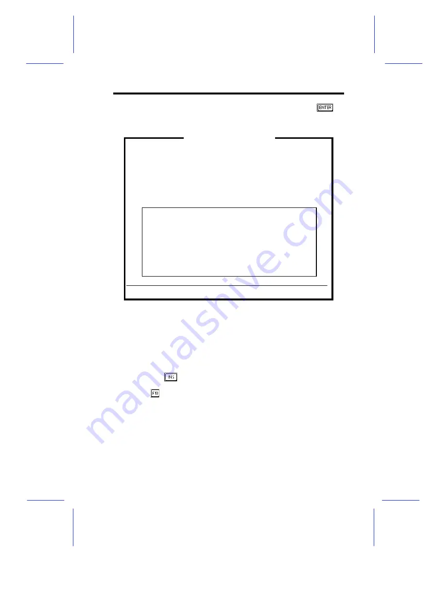
Figure 5-7
Add or Remove Boards
The screen contains the configuration data that the ECU read
from your CFG file. It includes the number of EISA slots and
device controllers detected.
7.
If you want to add or have already added a board, highlight a slot
and press
to select an option from the list that appears.
8.
Press
when done.
9.
Follow steps 4 to 13 in section 5.1.5 to complete your
configuration.
Step 2: Add or remove boards
Listed are the board and options detected in your computer.
Press INSERT to add the boards or options which could not be
detected or which you plan to install.
Press DEL to remove the highlighted board from your configuration.
Press F7 to move the highlighted board to another slot.
Press F10 when you have completed this step.
>
Add=INSERT
<
<Remove=DEL>
<Move=F7>
<Done=F10>
>
AcerAltos Server
Slot 1
(Empty)
Slot 2
(Empty)
Slot 3
(Empty)
Embedded PCI SCSI Controller
Summary of Contents for Apricot FT2200
Page 1: ...FT2200 NATIONAL ACCREDITATION OFCERTIFICATION BODIES System Guide...
Page 2: ...FT2200 System Guide...
Page 19: ...xviii...
Page 34: ...Setting Up the System 2 7 2 2 2 Mouse Figure 2 5 Connecting a Mouse...
Page 35: ...2 8 System Guide 2 2 3 VGA Monitor Figure 2 6 Connecting a VGA Monitor...
Page 37: ...2 10 System Guide 2 2 5 Power Cables Figure 2 8 Power Cables...
Page 79: ......
Page 80: ......
Page 124: ...apricot System Guide FT2200...


