Mitsubishi Electric CR800-D Series User Manual Download Page 61


Abnormality  detection  function  59 


How  to  check  the  motor  speed  with  the  RT  ToolBox3  monitor  function 


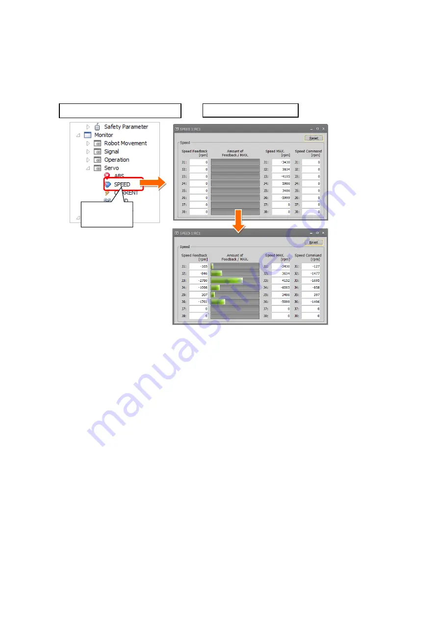
1) From the RT ToolBox3 project tree, click [Monitor] - [Servo] and then double-click [Speed] to 

display the [SPEED] screen. 

2) You can monitor data related to the speed of each axis motor of the robot in action. 

1) [Servo]   

[SPEED] 


1) Speed monitor screen


RT ToolBox3 project tree 


Summary of Contents for CR800-D Series

Page 1: ...CR800 D R Q series controller Predictive Maintenance Function User s Manual Mitsubishi Electric Industrial Robot BFP A3663 ...

Page 2: ......

Page 3: ...that teaching work is in progress on the start switch etc This also applies to maintenance work with the power source turned ON Indication of teaching work in progress DANGER Provide a fence or enclosure during operation to prevent contact of the operator and robot Installation of safety fence CAUTION Establish a set signaling method to the related operators for starting work and follow this metho...

Page 4: ...the rated load or permitted torque Exceeding either of these can cause an alarm or breakdown WARNING Securely install the hand and tool and securely grasp the workpiece Failure to observe this could lead to personal injuries or damage if the object comes off or flies off during operation WARNING Securely ground the robot and controller Failure to observe this could lead to malfunctioning by noise ...

Page 5: ...the robot regardless of whether the operation rights are enabled or not DANGER Do not connect the Handy GOT to a programmable controller when using an iQ Platform compatible product with the CR800 R CR800 Q controller Failure to observe this may result in property damage or bodily injury because the Handy GOT can automatically operate the robot regardless of whether the operation rights are enable...

Page 6: ...cturer The thing unsuitable for the FA environment related with conformity temperature or noise exists in the equipments connected to USB When using network equipment measures against the noise such as measures against EMI and the addition of the ferrite core may be necessary Please fully confirm the operation by customer Guarantee and maintenance of the equipment on the market usual office automa...

Page 7: ... Revisions Revision Date Instruction Manual No Revision Details 2019 04 25 BFP A3663 First print ...

Page 8: ...peration refer to the separate Instruction Manual Detailed Explanations of Functions and Operations Notation used in this manual Caution Warning Danger This indicates an item for which incorrect handling could present imminent danger of death or serious injury This indicates an item for which incorrect handling could present a danger of death or serious injury This indicates an item for which inco...

Page 9: ...g of maintenance simulation 44 4 Basic screen structure 48 5 Total score 50 6 Consumption degree calculation function 52 7 Abnormality detection function 56 8 Operating information 60 9 Maintenance simulation 62 9 1 1 Cycle operation 64 9 2 Program operation 70 10 When consumption occurred abnormality detected 74 10 1 Consumption Degree 74 10 1 1 Maintenance parts 74 10 1 2 Overhaul parts 75 10 1 ...

Page 10: ...Common to predictive maintenance functions 160 14 2 Consumption degree calculation function 161 14 2 1 Setting parameters 161 14 2 2 Data acquisition parameters 163 14 2 3 Operation parameters 167 14 3 Abnormality detection function 172 14 3 1 Setting parameters 172 14 3 2 Data acquisition parameters 173 14 3 3 Operation parameters 175 15 Dedicated input output signals 178 15 1 Consumption degree ...

Page 11: ...e initial setting method 4 Basic screen structure Each predictive maintenance function is explained using examples of the RT ToolBox3 Predictive maintenance screens 5 Total score 6 Consumption degree calculation function 7 Abnormality detection function 8 Operating information 9 Maintenance simulation 10 When consumption occurred abnormality detected Explains pause of warning occurrence related to...

Page 12: ... support software Note 1 RT ToolBox3 Ver 1 50C or later Robot program language MELFA BASIC VI RT ToolBox3 mini Note 2 Ver 1 50C or later RT ToolBox3 Pro Ver 1 50C or later 4 Function expansion card MELFA Smart Plus Card Pack Note 3 AB type 2F DQ520 Either one MELFA Smart Plus Card Note 3 B type 2F DQ521 Note 1 Must be purchased separately Note 2 When RT ToolBox3 mini is used simulation on RT ToolB...

Page 13: ...Series Controller Instruction Manual Troubleshooting Explains the causes and remedies to be taken when an error occurs Explanations are given for each error No RT ToolBox3 RT ToolBox3 mini User s Manual The operation manuals for the robot total engineering support software RT ToolBox3 RT ToolBox3 mini RT ToolBox3 Pro Option MELFA Smart Plus User s Manual Describes the installation method and setti...

Page 14: ...e are two types of maintenance and inspection daily inspection and periodic inspection The following table shows the type of maintenance and inspection Type of maintenance and inspection No Type of inspection and maintenance works Description Operating time Note1 1 Daily inspection Inspection works to be performed every day before starting operation for the safe use of the robot 2 Periodic inspect...

Page 15: ...ement period The timing belt life is greatly affected by the robot working conditions so a set time cannot be given However if the following symptoms occur replace the belt 1 The belt tension value becomes less than the guideline value 2 Position mismatch or gear teeth skipping occurs 3 Cracks or wear occurs on the belt 4 The tooth bottom of the belt is worn out and the core is exposed The timing ...

Page 16: ...ollowing table For details on overhaul refer to 1 4 5 About Overhaul Refer to 5 Maintenance and Inspection in the separate volume Instruction manual Robot Arm Setup Maintenance for lubrication locations lubrication specifications and lubrication methods Lubrication interval Robot type Lubrication interval RV 2FR RV 2FRL All axes 6 000 hr RV 4FR RV 4FRL RV 7FR RV 7FRL All axes 24 000 hr RV 7FRLL RV...

Page 17: ...e replaced periodically by the customer The guideline for replacing the battery is one year but this will differ according to the robot s usage state When a battery related error occurred replace the battery of the robot arm For details of battery related errors refer to 16 1 Error number list and 16 1 3 Abnormality detection function The robot arm battery replacement method differs depending on t...

Page 18: ...s a rule of thumb it is recommended that overhaul be carried out before the total amount of servo on time reaches the specified time 24 000 hours for the robot arm and 36 000 hours for the controller Refer to the figure below However the degree of the equipment s wear and deterioration presumably varies depending on their operating conditions Especially for operation with high load and frequency t...

Page 19: ...of robot components based on the actual operating status motor speed load status and others and displays notifies the period up to maintenance inspection or overhaul This supports efficient maintenance through notification of maintenance timing and deciding the maintenance priority order Target parts Maintenance parts Grease timing belt Overhaul parts Reduction gear bearing ball screw ball spline ...

Page 20: ...te Program operation While running a robot program automatically the parts replacement the parts replacement the recommended maintenance time is estimated based on the operation pattern from when the start button is pressed to when the end button is pressed Accurate 1 cycle start line and end line cannot be specified but Program operation is used when it is difficult to specify 1 cycle on the prog...

Page 21: ...that is automatically generated when 1 cycle operation is executed After 1 cycle operation you can delete this program if it is unnecessary When RT ToolBox3 mini is used simulation on RT ToolBox3 cannot be used The recommended number of years up to the replacement maintenance time output by this function is the value calculated when the specified operation is repeated Also the result may vary depe...

Page 22: ...on for each joint axis 1 Of the maintenance parts grease timing belt the Consumption Degree and Up to Maintenance h of the part joint axis having the least remaining time are used 2 Of the overhaul parts reduction gear bearing ball screw ball spline the Consumption Degree of the part joint axis having the least up to maintenance time is used Information confirmation Information Consumption Degree ...

Page 23: ...ence value for supporting the maintenance and inspection schedule calculated based on the robot operating status It does not guarantee the service life of the robot Irrespective of the consumption degree carry out daily inspection and periodic maintenance and inspection described in the instruction manual Standard Specifications Manual Robot Arm Setup Maintenance When the servo ON time exceeds the...

Page 24: ... maintenance forecast are not output When the information is reset by the predictive maintenance function or maintenance forecast the information in the other function is reset as well About the robot controller When using this function by upgrading from a non compatible controller software version to a compatible controller software version the consumption degree during the period of the non comp...

Page 25: ...Basic specifications 23 MEMO ...

Page 26: ...Notify setting abnormality detection Warning Occurrence Signal Output Level Setting reduction gear Level Setting encoder data error Level Setting encoder communication error I O Signals assignment Setting method RT ToolBox3 Predictive maintenance screen Refer to 3 2 1 Setting how to notify 3 2 2 Setting detection level Parameters Refer to 14 3 Abnormality detection function 14 3 1 Setting paramete...

Page 27: ...ores with the real time monitor oscillograph How to check the motor speed with the RT ToolBox3 monitor function When there is a vibration source outside the robot arm or robot operation is hindered by an external cable and others Abnormalities or deterioration of parts may not be diagnosed correctly Since the score of the reduction gear abnormality detection varies depending on the operating speed...

Page 28: ... RV 7FR RV 7FRL Joint axis J1 axis J2 axis J3 axis J4 axis J5 axis J6 axis Maintenance parts Grease Timing belt Overhaul parts Reduction gear Bearing Ball screw Ball spline 3 RV 13FR RV 13FRL RV 20FR RV 7FRLL Joint axis J1 axis J2 axis J3 axis J4 axis J5 axis J6 axis Maintenance parts Grease Timing belt Overhaul parts Reduction gear Bearing Ball screw Ball spline 4 RH 3FRH RH 6FRH RH 12FRH RH 20FR...

Page 29: ... function of each robot type are used Uses target parts x Not subject to abnormality detection 1 RV 2FR RV 2FRL Joint axis J1 axis J2 axis J3 axis J4 axis J5 axis J6 axis Reduction gear Encoder Battery 2 RV 4FR RV 4FRL RV 7FR RV 7FRL Joint axis J1 axis J2 axis J3 axis J4 axis J5 axis J6 axis Reduction gear Encoder Battery 3 RV 13FR RV 13FRL RV 20FR RV 7FRLL Joint axis J1 axis J2 axis J3 axis J4 ax...

Page 30: ...ance This function is useful for reviewing or planning a maintenance schedule For function details refer to 6 Consumption degree calculation function 7 Abnormality detection function 3 System operation time when a part is consumed As a result of the remaining time to replacement maintenance calculated by the consumption degree calculation function if the set remaining time is reached that effect i...

Page 31: ...Basic specifications 29 MEMO ...

Page 32: ...on code of the MELFA Smart Plus Card 5 Restart the robot controller 3 Set the MELFA Smart Plus enable parameter Initial setting of the predictive maintenance function 3 2 Validation of the predictive maintenance function 3 1 Maintenance simulation can be used Setting of maintenance simulation 3 3 6 Check if the predictive maintenance function is in enable state Consumption degree calculation Abnor...

Page 33: ...ightly hold the interface cover removal lever to pull out the interface cover 2 Hold the handle of the MELFA Smart Plus card and insert it into SLOT1 or SLOT2 At that time insert in such a way that both ends of the card fit into the groove of the slot SLOT1 or SLOT2 in the illustration 3 Insert the connection connector all the way to the end until the removal lever clicks into place to be locked M...

Page 34: ...rt Plus card flashes MELFA Smart Plus Card Flashes in red MELFA Smart Plus Card Pack Flashes in blue Selecting the MELFA Smart Plus function and setting the predictive maintenance function enable parameters 4 S e l e c ti n With a robot controller where the MELFA Smart Plus Card has been inserted set the MELFA Smart Plus function selection parameter SMART 1 and the predictive maintenance function ...

Page 35: ...t CPU system CR800 D type CR800 R Q type Check that the predictive maintenance function is enabled 6 1 When the MELFA Smart Plus card is used the LED of the MELFA Smart Plus card flashes green When the MELFA Smart Plus card pack is used the LED flashes blue 2 Check that the predictive maintenance function has been enabled For the teaching pendant Check that the MSPPMENB parameter is set to 1 For R...

Page 36: ...r message are displayed according to the situation Signal Output The status can be checked with dedicated output signals Setting of signal numbers are required Refer to 3 2 3 Setting signals 2 Notification day Warning Remaining Number of Days Set the number of remaining days for warning to occur Operation Time of a Day Set the number of hours of operation of the robot per day 3 Notification interv...

Page 37: ...etection level 6 Write Writes setting items on the robot controller 3 2 2 Setting detection level 1 Detection level Set the detection level of J1 to J6 2 Reset The detection level set in 1 above is reset to the default settings 3 Oscillograph Starts the RT ToolBox3 Oscillograph screen 4 Setting Reflects the values on the screen to the parameters Set detection level 8 When you click the Detail butt...

Page 38: ...sidering variations The score may fluctuate when the robot is restarted Procedure 1 Operate the robot under the actual operating conditions and collect score data for about 7 to 30 days 2 Check the maximum score of the log data 365 days worth of the maximum score of the day can be saved as log data Log data can be checked by going to Comprehensive Abnormality detection Gear Refer to 7 Abnormality ...

Page 39: ...maximum score 180 08 from 7 days worth of log data after starting operation An error was detected and notified by a warning and signal that were output because the score exceeded the predetermined detection level 9 days Log No 10 before the robot stopped At that point no unusual noises or faults were detected Later an unusual noise was detected and the robot started to fail and finally stopped 9 d...

Page 40: ... retained After replacing the motor if you reset the score of the replaced axis its score becomes 0 Since miscount and communication failure sometimes occur due to noise and others set the detection level of the encoder data communication score with some margin 100 Detection level set by you Example display of encoder communication abnormality log data Example display 1 Example display 2 100 1 0 0...

Page 41: ...via Ethernet If data cannot be obtained by this method check Q A connection Ethernet in the separate RT ToolBox3 RT ToolBox3 mini User s Manual 1 Start up the oscillograph on RT ToolBox3 1 From the Predictive maintenance Synthesis screen click Level Setting at the right side of the Abnormality Detection How to Notify area 2 The Level Setting screen is displayed Click the Oscillograph button to sta...

Page 42: ...ed in the Communication Setting screen is displayed at the left side of Oscillograph 2 You can set the item to be displayed in the real time monitor on the Graph setting screen 3 You can set the display range of the vertical axis of each data on the Range setting screen When you select Auto Adjust the vertical axis of the graph is automatically adjusted Predictive maintenance score gear encoder da...

Page 43: ... on graph Example When you set the display points to Time scale 10minutes the data created for 10 minutes is displayed on the graph Since the score reduction gear changes slowly by setting Time scale 10minutes for the display points it is easy to check convergence of the score value 1 Select Display Points Example Time scale 10minutes Example Displaying 10 min data on 1 screen 2 When you move the ...

Page 44: ...w a program or feature through Windows Firewall for Windows7 2 Check if there is RT ToolBox3 and communication range of the use environment in the Allowed programs and features list Solution 1 If RT ToolBox3 is not in the Allowed programs and features list click the Allow another program button If the Allow another program button is disabled click the Change settings button first 2 Select and add ...

Page 45: ...e Maintenance Predictive Maintenance 2 From the Predictive Maintenance tree click Setting Signal 3 Enter the signal number for the item to be set Note 1 4 When setting an axis bit pattern for reset pause click IODATA Setting When IODATA Setting screen appears set necessary information and click Write 5 After changing the parameter values click the Write button to write them to the robot controller...

Page 46: ...ect Parameter List 3 Enter MSPCODE for the parameter name on the Parameter List screen 4 The function code 24 alphanumeric characters of the MELFA Smart Plus Card is displayed write it down in a memo First get the function code from the robot controller where the MELFA Smart Plus card and predictive maintenance function have been enabled 3 1 Enabling the predictive maintenance function is complete...

Page 47: ...unction code field 5 Press the Set button 6 Press the OK button and restart RT ToolBox3 Next enter the function code obtained in Step 1 to the RT ToolBox3 that performs the maintenance simulation 2 Option 4 Enter the function code 3 MELFA Smart Plus Option screen 5 Setting 6 OK Set the predictive maintenance function enable parameter 3 Set the parameter to enable predictive maintenance 1 Open the ...

Page 48: ...ange the operation mode to Simulation If parameter setting in Step 3 is performed using Simulation start up Simulation once again The PMENA parameter requires rebooting 2 From the project tree expand Maintenance and check that Predictive Maintenance is displayed Predictive Maintenance Maintenance ...

Page 49: ...Startup and initial settings 47 MEMO ...

Page 50: ...he Total Score screen the predictive maintenance function tree is displayed on the left side and the main screen on the right side 3 When you click the mark in the predictive maintenance function tree menus of the predictive maintenance function appear 4 When you click an item on the predictive maintenance function tree the main screen on the right changes Predictive Maintenance is displayed under...

Page 51: ...integration time and accumulation count from the time when the previous overhaul was carried out Integration Time hours Power ON Time Servo ON Time Operation Time Actual Operation Time Accumulation Count times Servo ON Count Motor Cumulative Rotation Count For details refer to 8 Operating information 5 Maintenance simulation Using the real machine online or simulations on RT ToolBox3 this function...

Page 52: ...ce parts Grease timing belt Consumption degree remaining time up to the recommended maintenance time The remaining time of each joint axis of maintenance parts is calculated and Consumption Degree and Up to Maintenance h of the part joint axis having the least remaining time to the recommended maintenance time is displayed Overhaul parts Reduction gear bearing ball screw ball spline Consumption de...

Page 53: ... the setting value is not appropriate 2 Due to operating environment The robot installation location or robot motion was changed Effect of vibration around the robot or electric noise If the above factors are not considered as the cause check the change in the score of the log on the Abnormality Detection screen or the current status from the oscillograph 3 Predictive maintenance message When the ...

Page 54: ...reduction gear bearing ball screw ball spline is displayed separately in two screens Also the current status is displayed as the predictive maintenance message Maintenance parts and overhaul parts Maintenance parts Grease timing belt Overhaul parts Reduction gear bearing ball screw ball spline 1 Start predictive maintenance 2 Click Total Score Consumption Degree to expend the menu 3 When you selec...

Page 55: ...upporting the maintenance and inspection schedule calculated based on the robot operating status It does not guarantee the service life of the robot Irrespective of the consumption degree carry out daily inspection and periodic maintenance and inspection described in the instruction manual Standard Specifications Manual Robot Arm Setup Maintenance When the servo ON time exceeds the specified time ...

Page 56: ...signals of maintenance forecast are not output When the information is reset by the predictive maintenance function or maintenance forecast the information in the other function is reset as well Caution Caution Caution About the robot controller When using this function by upgrading from a non compatible controller software version to a compatible controller software version the consumption degree...

Page 57: ...Consumption degree calculation function 55 MEMO ...

Page 58: ...ays log data of the maximum value of score of each joint axis for the past 365 days The indicated value is the maximum value of a day You can specify the display period using the Display Period field of the upper part of the screen Non target axes are not displayed The color of the graph differs depending on the score The color is blue when the latest value of the score is normal When the value ex...

Page 59: ... days 5 Update Updates the screen display 6 Output CSV Output the graph data displayed on the screen date and score in the CSV format Storage destination and file name of the CSV file Storage destination Folder for workspace Project name Maintenance PMLog File name DetectionDataYYYYMMD HHMMSS csv Green line Detection level set by you Example display 1 Score current value The score is under the abn...

Page 60: ...conditions mis detection may occur or abnormalities may not be detected Use parameters HNDDAT and WRKDAT to set hand work conditions and use Loadset commands to specify hand work conditions For details of hand work condition setting refer to the separate Instruction Manual Detailed Explanations of Functions and Operations The reduction gear abnormality detection function calculates when the motor ...

Page 61: ...Box3 monitor function 1 From the RT ToolBox3 project tree click Monitor Servo and then double click Speed to display the SPEED screen 2 You can monitor data related to the speed of each axis motor of the robot in action 1 Servo SPEED 1 Speed monitor screen RT ToolBox3 project tree ...

Page 62: ...ta Unit Integration Time Power ON Time duration of robot controller power ON h hours Servo ON Time duration of servo ON h hours Operation Time duration of robot program execution h hours Actual Operation Time duration of actual robot arm operation h hours Accumulation Count Servo ON Count robot times Motor Cumulative Rotation Count for robot each joint axis r rotation 1 Start predictive maintenanc...

Page 63: ...Operating information 61 MEMO ...

Page 64: ...it is possible to more accurately estimate the number of years when 1 cycle operation is repeated than when using Program operation The estimation result of the number of years is from the brand new robot state Program operation While running a robot program automatically the parts replacement the recommended time is estimated based on the operation pattern from when the start button is pressed to...

Page 65: ...itions weight center of gravity shape actually used If the settings differ from the actual robot settings the consumption degree cannot be calculated correctly Use parameters HNDDAT and WRKDAT to set hand work conditions and use Loadset commands to specify hand work conditions For details of hand work condition setting refer to the separate Instruction Manual Detailed Explanations of Functions and...

Page 66: ...d settings required for the robot to perform 1 cycle operation are included in the range When sending receiving external signals temporarily set the stop time as a substitute for the signal sending receiving time and specify the line numbers including that line Example If there is no jumping destination of a sub routine within the selected range an error jumping destination does not exist occurs a...

Page 67: ...nt position of the robot to the start position of 1 Cycle operation Example moving methods of the current position of the robot are described below Use direct execution to move the robot to the operation start position Use step operation to execute up to the start line of 1 Cycle operation Execute 1 Cycle operation once Step 2 to Step 7 and use the maintenance simulation results of the second and ...

Page 68: ...lation screen 1 Cycle Select the execution program 4 1 Click Program Selection on the Maintenance Simulation screen 2 The Select Robot Program screen opens select the program to run the simulation and click the OK button Maintenance Simulation screen Program selection Select Robot Program screen Select the program ...

Page 69: ...After resetting the error execute Step 1 to adjust the robot posture to the start posture and then execute again from Step 3 Select Program Line Number screen 2 Line number input box 3 Starts estimation Click to input line numbers Caution Robot program is executed 6 1 The status of the operating panel indicates During maintenance simulation and the robot program is indicated as ESTPROG and 1 cycle...

Page 70: ...splayed 3 When you click the Save button output maintenance simulation results in the CSV format Storage destination and file name of the CSV file Storage destination Folder for workspace Project name Maintenance PMLog File name SimulationDataYYYYMMD HHMMSS csv 4 Click the Retry button to return to the initial screen of maintenance simulation 5 The graph and the number of years are not displayed f...

Page 71: ...00 The calculated axis load level assumes multiple iterations of the same operation However be aware that stop will not occur in simulation even if the load level exceeds 100 There is a possibility that continuous operation will not be possible in an actual robot when the calculated axis load level is high You should lower the operation frequency with the Dly command and lower operation speed and ...

Page 72: ...eration for the program Execution program Starts automatic operation Open the Maintenance Simulation screen 1 While automatically running the program that performs maintenance simulation from the RT ToolBox3 project tree click Maintenance Predictive Maintenance to start 2 From the predictive maintenance tree select Maintenance Simulation Note When an actual machine is connected the 1 Cycle button ...

Page 73: ...n 1 Clicking the Start button on the Maintenance Simulation screen starts maintenance simulation During simulation a During maintenance simulation message is displayed under the Start button 4 On the operation panel Operating is displayed for Status and the currently running program name is displayed for Program In case of simulation mode robot motion can be checked on the 3D monitor Maintenance S...

Page 74: ...erforming maintenance simulation have been executed click the End button on the Maintenance Simulation screen The maintenance simulation ends and the Maintenance Simulation result screen appears Even though the End button is clicked the robot continues operation Maintenance Simulation screen End ...

Page 75: ... destination Folder for workspace Project name Maintenance PMLog File name SimulationDataYYYYMMD HHMMSS csv 4 Click the Retry button to return to the initial screen of maintenance simulation 5 The graph and the number of years are not displayed for joint axes that do not use the target parts The number of years up to the replacement time of grease and the timing belt are displayed Also for overhau...

Page 76: ...ntinues to be displayed if the consumption status or abnormal status is unchanged 10 1 Consumption Degree 10 1 1 Maintenance parts 1 Grease n in the table indicates the axis numbers 1 to 6 Error number C 712n Error message Grease replenishment period RT ToolBox3 predictive maintenance message The grease Jn axis consumption degree exceeded the warning number of days remaining Please check the detai...

Page 77: ...e refer to 5 Maintenance and Inspection in the separate volume Instruction Manual Robot Arm Setup Maintenance For reset method refer to 11 2 Maintenance Reset 10 1 2 Overhaul parts 1 Reduction gear n in the table indicates the axis numbers 1 to 6 Error number C 714n Error message Overhaul period decelerator RT ToolBox3 predictive maintenance message The gear Jn axis consumption degree exceeded the...

Page 78: ... our service affiliated company After overhaul perform reset For reset method refer to 11 2 Maintenance Reset 3 Ball screw Error number C 716n Error message Overhaul period ball screw RT ToolBox3 predictive maintenance message The ball screw Jn axis consumption degree exceeded the warning number of days remaining Please check the details and prepare for overhaul Measures Perform overhaul of the ro...

Page 79: ...pany After overhaul perform reset For reset method refer to 11 2 Maintenance Reset Error number C 7110 Error message Overhaul period servo on time RT ToolBox3 predictive maintenance message The servo on time exceeded recommended overhaul time Overhaul is recommended Measures Perform overhaul of the robot body For selection of replacement parts and overhaul implementation timing consult with our se...

Page 80: ...Note1 For inspection replacement of parts consult with our service affiliated company If you replace a part perform reset For reset method refer to 11 2 Maintenance Reset Error number C 719n Error message Abnormality detection encoder com RT ToolBox3 predictive maintenance message The warning of the encorder communication Jn axis failure was detected Check the details and perform maintenance and i...

Page 81: ...n Manual Robot Arm Setup Maintenance Error number C 7500 Error message No battery voltage robot RT ToolBox3 predictive maintenance message Battery voltage outage detected Please replace the battery immediately If the power is turned on again without replacing the battery the absolute position data of the encoder may be lost Measures Replace the battery as soon as possible When the home position ha...

Page 82: ...ntenance Reset Resets clears the accumulation data related to consumption degree and score 3 Backup Performs backup restore when migrating the predictive maintenance data to a different controller 4 Maintenance Log Displays the maintenance log recorded during executing maintenance reset 1 Start predictive maintenance 2 Click Maintenance to expand the menu the maintenance functions are displayed 3 ...

Page 83: ...check box to pause Deselect this check box to cancel pause 4 Pause Method of Warning Occurrence Signal Output Set the pause method of warning occurrence 5 Write Writes the content of the selected item You can temporarily disable notification related to consumption degree calculation until part replacement reset of consumption degree You can also temporarily disable notification related to abnormal...

Page 84: ...e calculation of the specified joint axis Score of the reduction gear abnormality detection of the specified joint axis Note 1 Timing belt At part replacement Reduction gear Bearing Ball screw ball spline Overhaul At overhaul Accumulated data of all parts operating information integration time and accumulation count Score of abnormality detection of all parts Mechanism replacement At replacement o...

Page 85: ... back up the predictive maintenance information from the previous controller and restore it in the new controller Exchanging the combination of robot controller and mechanism between the same models When exchanging the combination of controller and mechanism between the same models before implementation back up the predictive maintenance information of the respective controllers and after implemen...

Page 86: ... is output upon power on to notify that effect in order to prevent the occurrence of unmatched predictive maintenance information when exchanging robot When there is no backup data all consumption degrees can be reset by performing mechanism replacement of maintenance reset However in that case the consumption degree calculation result cannot be the correct value Refer to 11 2 Maintenance Reset Af...

Page 87: ...back up predictive maintenance information Create a backup file for predictive maintenance information 1 1 Start predictive maintenance 2 Click Maintenance Backup 3 When you click Backup on the main screen the Select Backup Folder screen opens and click the OK button Storage destination and the folder name of the backup data Storage destination Folder for workspace Project name Maintenance PMLog F...

Page 88: ...e predictive maintenance information 1 1 Start predictive maintenance 2 Click Maintenance Backup 3 When Restore is clicked on the main screen the Select Backup Folder appears 4 Use the Browse button to specify the location of the backup folder 5 The backup folder is displayed on the screen select the folders you wish to restore and then press the OK button 6 From the tree on the left side when you...

Page 89: ...rgets Grease timing belt reduction gear bearing ball screw overhaul 1 Select Parts Select items for which a log is displayed All Grease Timing Belt Gear Bearing Ball Screw Overhaul 2 Component Items selected in the Select Parts field are displayed A maximum of 10 log items are displayed for each axis 3 Axis Number Displays the target axes Displays for overhaul 4 Date Displays the reset date time 5...

Page 90: ...degree at the time of reset Timing belt Reduction gear Bearing Ball screw Ball spline Overhaul Robot Reset date time servo ON time h at the time of reset Note1 Reset implementation count Note1 For each joint axis Grease timing belt reduction gear bearing ball screw ball spline overhaul Note 1 You can check them by robot system status variables or parameters The maintenance log of each part and the...

Page 91: ...Maintenance 89 MEMO ...

Page 92: ...o be output refer to 12 2 Output data Communication protocol Details Data acquisition method MelfaRXM ocx This is ActiveX control that communicates with the robot controller used when you create application software to communicate with the robot controller The instruction manual is included in the following folder in the CD ROM of RT ToolBox3 Standard Version Pro Version Communication Middleware M...

Page 93: ...Reduction gear M_PMCsmDec CSMPMDEC Bearing M_PMCsmBrg CSMPMBRG Ball screw Ball spline M_PMCsmBss CSMPMBSS Remaining time Mechanism total maintenance parts h hours M_PMRmnMnt RMNPMMNT Servo ON time At overhaul implementation h hours M_PMRmnSrv RMNPMSRV Consumption status Mechanism total maintenance parts M_PMStsMnt STSPMMNT Mechanism total overhaul parts M_PMStsOH STSPMOH Grease M_PMStsGrs STSPMGRS...

Page 94: ...n abnormality M_PMScrEnc2 SCRPMEN2 Abnormality detection status Reduction gear M_PMStsDrv STSPMDRV Encoder data abnormality M_PMStsEnc1 STSPMEN1 Encoder communication abnormality M_PMStsEnc2 STSPMEN2 Battery voltage status M_PMStsBat STSPMBAT Notification method of abnormality detection Pause status Reduction gear M_PMRptDrv RPTPMDRV Encoder data abnormality M_PMRptEnc1 RPTPMEN1 Encoder communicat...

Page 95: ... specified by RequestService You can get robot status variables and parameter values related to the predictive maintenance function using the existing request ID ID value Function name 212 Get variable value 301 Get parameter value consider open level 302 Write parameter value ...

Page 96: ... Double precision real number type 107 Maintenance log Variable name Array designation Details Attribute 1 Data type Unit Page M_PMLogGrs Axis No 1 to 8 Maintenance count grease R Integer type 108 M_PMLogBlt Axis No 1 to 8 Maintenance count timing belt R Integer type 109 M_PMLogDec Axis No 1 to 8 Maintenance count reduction gear R Integer type 110 M_PMLogBrg Axis No 1 to 8 Maintenance count bearin...

Page 97: ...umption degree ball screw ball spline R Single precision real number type 126 M_PMRmnMnt None Remaining time mechanism total maintenance parts R Integer type Time 127 M_PMRmnSrv None Remaining time servo ON time R Integer type Time 128 Consumption status Variable name Array designation Details Attribute 1 Data type Unit Page M_PMStsMnt None Consumption status mechanism total maintenance parts R In...

Page 98: ...t Axis No 1 to 8 Notification pause status timing belt R Integer type 138 M_PMRptDec Axis No 1 to 8 Notification pause status reduction gear R Integer type 139 M_PMRptBrg Axis No 1 to 8 Notification pause status bearing R Integer type 140 M_PMRptBss Axis No 1 to 8 Notification pause status ball screw ball spline R Integer type 141 M_PMRptSrv None Notification pause status servo ON time R Integer t...

Page 99: ..._PMScrEnc1 Axis No 1 to 8 Score encoder data abnormality R Single precision real number type 148 M_PMScrEnc2 Axis No 1 to 8 Score encoder communication abnormality R Single precision real number type 149 Abnormality detection status Variable name Array designation Details Attribute 1 Data type Unit Page M_PMStsDrv Axis No 1 to 8 Abnormality detection status reduction gear R Integer type 150 M_PMSt...

Page 100: ... Unit Page M_PMWngDrv Axis No 1 to 8 Detection level reduction gear abnormality detection R Integer type 157 M_PMWngEnc1 Axis No 1 to 8 Detection level encoder data abnormality detection R Integer type 158 M_PMWngEnc2 Axis No 1 to 8 Detection level encoder communication abnormality detection R Integer type 159 ...

Page 101: ... 1 Data type Unit Page M_SmartPlus 2 1 MELFA Smart Plus function usage status R Integer type C_SmartPlus 2 1 MELFA Smart Plus function name R Character string type 1 Attributes in the table R Read only 2 For the Robot system status variable of MELFA Smart Plus card refer to the separate volume Instruction Manual MELFA Smart Plus ...

Page 102: ...e C_RBSerial Mechanism number Terminology String variable Specify the string variable to assign Mechanism number Set the mechanism number 1 to 3 When omitted 1 is used Sample 1 C1 C_RBSerial 1 The serial number of the robot body mechanism 1 is set in C1 Explanation 1 Returns the serial number of the robot body registered in the RBSERIAL parameter 2 This variable is read only Related system status ...

Page 103: ...ller Format Example String variable C_RCSerial Terminology String variable Specify the string variable to assign Sample 1 C1 C_RCSerial The serial number of the robot controller is set in C1 Explanation 1 Returns the serial number of the robot controller 2 This variable is read only Related system status variables C_RBSerial ...

Page 104: ...OnTime Terminology Numeric variable Specify the numeric variable to assign Sample 1 M1 M_PowOnTime The cumulative time of power ON of the robot controller is set in M1 Explanation 1 Returns the cumulative time of power ON of the robot controller The cumulative time is the time from when the previous overhaul was carried out 2 This variable is read only 3 Returns 1 when the predictive preventive ma...

Page 105: ...ic variable Specify the numeric variable to assign Sample 1 M1 M_SrvOnTime The cumulative servo ON time of the robot body mechanism 1 is set in M1 Explanation 1 Returns the cumulative time of servo ON of the robot body mechanism 1 The cumulative time is the time from when the previous overhaul was carried out 2 This variable is read only 3 Returns 1 when the predictive preventive maintenance funct...

Page 106: ..._PrgTime Terminology Numeric variable Specify the numeric variable to assign Sample 1 M1 M_PrgTime The operation time of the robot controller is set in M1 Explanation 1 Returns the operation time of the robot controller The operation time is the time from when the previous overhaul was carried out 2 This variable is read only 3 Returns 1 when the predictive preventive maintenance function is disab...

Page 107: ...gy Numeric variable Specify the numeric variable to assign Sample 1 M1 M_MovTime The actual operation time of the robot body mechanism 1 is set in M1 Explanation 1 Returns the actual operation time of the robot body mechanism 1 The actual operation time is the time from when the previous overhaul was carried out 2 This variable is read only 3 Returns 1 when the predictive preventive maintenance fu...

Page 108: ...gy Numeric variable Specify the joint type variable to assign Sample 1 M1 M_SrvOnNum The servo ON count of the robot body mechanism 1 is set in M1 Explanation 1 Returns the servo ON count of the robot body mechanism 1 The count is the accumulation count from when the previous overhaul was carried out 2 This variable is read only 3 Returns 1 when the predictive preventive maintenance function is di...

Page 109: ...number Specify the joint axis to get the cumulative rotation count 1 to 6 When omitted 1 is used Sample 1 M1 M_MtRotNum 1 The motor cumulative rotation count of the J1 axis is set in M1 Explanation 1 Returns the motor cumulative rotation count of the robot body mechanism 1 The rotation count is the accumulation count from when the previous overhaul was carried out 2 This variable is read only 3 Re...

Page 110: ...assign Axis number Specify the joint axis for which to get a log 1 to 6 When omitted 1 is used Sample 1 M1 M_PMLogGrs 1 The maintenance count of the grease for the J1 axis is set in M1 Explanation 1 Returns the maintenance count reset count of the grease for the robot body mechanism 1 2 This variable is read only 3 Returns 1 when the predictive preventive maintenance function is disabled 4 Returns...

Page 111: ...Axis number Specify the joint axis for which to get a log 1 to 6 When omitted 1 is used Sample 1 M1 M_PMLogBlt 1 The maintenance count of timing belt for the J1 axis is set in M1 Explanation 1 Returns the maintenance count reset count of timing belt of the robot body mechanism 1 2 This variable is read only 3 Returns 1 when the predictive preventive maintenance function is disabled 4 Returns 0 whe...

Page 112: ...number Specify the joint axis for which to get a log 1 to 6 When omitted 1 is used Sample 1 M1 M_PMLogDec 1 The maintenance count of the reduction gear for the J1 axis is set in M1 Explanation 1 Returns the maintenance count reset count of the reduction gear of the robot body mechanism 1 2 This variable is read only 3 Returns 1 when the predictive preventive maintenance function is disabled 4 Retu...

Page 113: ...s number Specify the joint axis for which to get a log 1 to 6 When omitted 1 is used Sample 1 M1 M_PMLogBrg 1 The maintenance count of the bearing of the J1 axis is set in M1 Explanation 1 Returns the maintenance count reset count of the bearing of the robot body mechanism 1 2 This variable is read only 3 Returns 1 when the predictive preventive maintenance function is disabled 4 Returns 0 when a ...

Page 114: ...gn Axis number Specify the joint axis for which to get a log 1 to 6 When omitted 1 is used Sample 1 M1 M_PMLogBss 3 The maintenance count of the ball screw of the J3 axis is set in M1 Explanation 1 Returns the maintenance count reset count of the ball screw ball spline of the robot body mechanism 1 2 This variable is read only 3 Returns 1 when the predictive preventive maintenance function is disa...

Page 115: ...MLogOH Terminology Numeric variable Specify the numeric variable to assign Sample 1 M1 M_PMLogOH The maintenance count of overhaul is set in M1 Explanation 1 Returns the maintenance count reset count of overhaul for the robot body mechanism 1 2 This variable is read only 3 Returns 1 when the predictive preventive maintenance function is disabled Related system status variables C_PMLogOH ...

Page 116: ...e 1 C1 C_PMLogGrs 1 1 The maintenance log of the grease is set in C1 Explanation 1 Returns the maintenance log data reset date time consumption degree at the time of reset of the grease for the robot body mechanism 1 2 This variable is read only 3 Returns 1 000 when the predictive preventive maintenance function is disabled 4 Returns Date Time Consumption degree at the time of reset when the predi...

Page 117: ...le 1 C1 C_PMLogBlt 1 1 The maintenance log of the timing belt is set in C1 Explanation 1 Returns the maintenance log data reset date time consumption degree at the time of reset of the timing belt of the robot body mechanism 1 2 This variable is read only 3 Returns 1 000 when the predictive preventive maintenance function is disabled 4 Returns Date Time Consumption degree at the time of reset when...

Page 118: ... 1 C1 C_PMLogDec 1 1 The maintenance log of the reduction gear is set in C1 Explanation 1 Returns the maintenance log data reset date time consumption degree at the time of reset of the reduction gear for the robot body mechanism 1 2 This variable is read only 3 Returns 1 000 when the predictive preventive maintenance function is disabled 4 Returns Date Time Consumption degree at the time of reset...

Page 119: ...le 1 C1 C_PMLogBrg 1 1 The maintenance log of the bearing is set in C1 Explanation 1 Returns the maintenance log data reset date time consumption degree at the time of reset of the bearing of the robot body mechanism 1 2 This variable is read only 3 Returns 1 000 when the predictive preventive maintenance function is disabled 4 Returns Date Time Consumption degree at the time of reset when the pre...

Page 120: ... 1 C1 C_PMLogBss 1 3 The maintenance log of the ball screw of the J3 axis is set in C1 Explanation 1 Returns the maintenance log data reset date time consumption degree at the time of reset of the ball screw ball spline of the robot body mechanism 1 2 This variable is read only 3 Returns 1 000 when the predictive preventive maintenance function is disabled 4 Returns Date Time Consumption degree at...

Page 121: ...fy 1 When omitted 1 is used Sample 1 C1 C_PMLogOH 1 The maintenance log of overhaul is set in C1 Explanation 1 Returns the maintenance log data reset date time servo ON time at the time of reset of overhaul for the robot body mechanism 1 2 This variable is read only 3 Returns 1 when the predictive preventive maintenance function is disabled 4 Returns Date Time Servo ON time h at the time of reset ...

Page 122: ...PMCsmMnt Terminology Numeric variable Specify the numeric variable to assign Sample 1 M1 M_PMCsmMnt The overall consumption degree of the maintenance parts is set in M1 Explanation 1 Returns the overall consumption degree of the maintenance parts grease timing belt of the robot body mechanism 1 2 This variable is read only 3 Returns 1 when the predictive preventive maintenance function is disabled...

Page 123: ...ric variable Specify the numeric variable to assign Sample 1 M1 M_PMCsmOH The overall consumption degree of the overhaul parts is set in M1 Explanation 1 Returns the overall consumption degree of the parts reduction gear bearing ball screw ball spline requiring overhaul of the robot body mechanism 1 2 This variable is read only 3 Returns 1 when the predictive preventive maintenance function is dis...

Page 124: ...to get the cumulative rotation count 1 to 6 When omitted 1 is used Sample 1 M1 M_PMCsmGrs 1 The consumption degree of the grease for the J1 axis is set in M1 Explanation 1 Returns the consumption degree unit of the grease of each joint axis of the robot body mechanism 1 2 This variable is read only 3 Returns 1 when the predictive preventive maintenance function is disabled 4 Returns 0 when a nonex...

Page 125: ...is to get the cumulative rotation count 1 to 6 When omitted 1 is used Sample 1 M1 M_PMCsmBlt 1 The consumption degree of the timing belt of the J1 axis is set in M1 Explanation 1 Returns the consumption degree unit of the timing belt of each joint axis of the robot body mechanism 1 2 This variable is read only 3 Returns 1 when the predictive preventive maintenance function is disabled 4 Returns 0 ...

Page 126: ... to get the cumulative rotation count 1 to 6 When omitted 1 is used Sample 1 M1 M_PMCsmDec 1 The consumption degree of the reduction gear of the J1 axis is set in M1 Explanation 1 Returns the consumption degree unit of the reduction gear of each joint axis of the robot body mechanism 1 2 This variable is read only 3 Returns 1 when the predictive preventive maintenance function is disabled 4 Return...

Page 127: ...is to get the cumulative rotation count 1 to 6 When omitted 1 is used Sample 1 M1 M_PMCsmBrg 1 The consumption degree of the bearing of the J1 axis is set in M1 Explanation 1 Returns the consumption degree unit of the bearing of each joint axis of the robot body mechanism 1 2 This variable is read only 3 Returns 1 when the predictive preventive maintenance function is disabled 4 Returns 0 when a n...

Page 128: ...int axis to get the cumulative rotation count 1 to 6 When omitted 1 is used Sample 1 M1 M_PMCsmBss 3 The consumption degree of the ball screw of the J3 axis is set in M1 Explanation 1 Returns the consumption degree unit of the ball screw ball spline of each joint axis of the robot body mechanism 1 2 This variable is read only 3 Returns 1 when the predictive preventive maintenance function is disab...

Page 129: ...iable M_PMRmnMnt Terminology Numeric variable Specify the numeric variable to assign Sample 1 M1 M_PMRmnMnt The remaining time up to the maintenance of the maintenance part is set in M1 Explanation 1 Returns the remaining time up to the maintenance of the maintenance parts grease timing belt of the robot body mechanism 1 2 This variable is read only 3 Returns 1 when the predictive preventive maint...

Page 130: ... Numeric variable M_PMRmnSrv Terminology Numeric variable Specify the numeric variable to assign Sample 1 M1 M_PMRmnSrv The remaining time up to overhaul of the overhaul part is set in M1 Explanation 1 Returns the remaining time of the cumulative servo ON time to reach the specified overhaul time 2 This variable is read only 3 Returns 1 when the predictive preventive maintenance function is disabl...

Page 131: ...f the maintenance parts is set in M1 Explanation 1 Returns the consumption status of the maintenance part grease timing belt of the robot body mechanism 1 0 The remaining time exceeded the warning occurrence remaining time 1 The remaining time is less than the warning occurrence remaining time exceeded 0 h 2 The remaining time is 0 h or less 2 Specify the warning occurrence remaining time using th...

Page 132: ...n status of the overhaul part is set in M1 Explanation 1 Returns the consumption status of the maintenance part grease timing belt requiring overhaul of the robot body mechanism 1 0 The remaining time exceeded the warning occurrence remaining time 1 The remaining time is less than the warning occurrence remaining time exceeded 0 h 2 The remaining time is 0 h or less 2 Specify the warning occurrenc...

Page 133: ...e consumption status of the grease for the J1 axis is set in M1 Explanation 1 Returns the consumption status of the grease of each joint axis of the robot body mechanism 1 0 The remaining time exceeded the warning occurrence remaining time 1 The remaining time is less than the warning occurrence remaining time exceeded 0 h 2 The remaining time is 0 h or less 2 This variable is read only 3 Returns ...

Page 134: ... The consumption status of the timing belt of the J1 axis is set in M1 Explanation 1 Returns the consumption status of the timing belt of each joint axis of the robot body mechanism 1 0 The remaining time exceeded the warning occurrence remaining time 1 The remaining time is less than the warning occurrence remaining time exceeded 0 h 2 The remaining time is 0 h or less 2 This variable is read onl...

Page 135: ...he consumption status of the reduction gear of the J1 axis is set in M1 Explanation 1 Returns the consumption status of the reduction gear of each joint axis of the robot body mechanism 1 0 The remaining time exceeded the warning occurrence remaining time 1 The remaining time is less than the warning occurrence remaining time exceeded 0 h 2 The remaining time is 0 h or less 2 This variable is read...

Page 136: ... The consumption status of the bearing of the J1 axis is set in M1 Explanation 1 Returns the consumption status of the bearing of each joint axis of the robot body mechanism 1 0 The remaining time exceeded the warning occurrence remaining time 1 The remaining time is less than the warning occurrence remaining time exceeded 0 h 2 The remaining time is 0 h or less 2 This variable is read only 3 Retu...

Page 137: ...sBss 3 The consumption status of the ball screw of the J3 axis is set in M1 Explanation 1 Returns the consumption status of the ball screw ball spline of each joint axis of the robot body mechanism 1 0 The remaining time exceeded the warning occurrence remaining time 1 The remaining time is less than the warning occurrence remaining time exceeded 0 h 2 The remaining time is 0 h or less 2 This vari...

Page 138: ...PMStsSrv The arrival status to the specified overhaul time is set in M1 Explanation 1 Returns the arrival status of the cumulative servo ON time to the specified overhaul time for the robot body mechanism 1 0 The remaining time exceeded the warning occurrence remaining time 1 The remaining time is less than the warning occurrence remaining time exceeded 0 h 2 The remaining time is 0 h or less 2 Th...

Page 139: ...et a log 1 to 6 When omitted 1 is used Sample 1 M1 M_PMRptGrs 1 The notification method of the grease consumption of the J1 axis is set in M1 Explanation 1 Returns the pause status of warning occurrence warning signal output which occurs due to grease consumption of the joint axis specified in Axis number of the robot body mechanism 1 1 0 Enable Disable 2 This variable is read only 3 Returns 1 whe...

Page 140: ... 1 to 6 When omitted 1 is used Sample 1 M1 M_PMRptBlt 1 The notification method of the timing belt consumption of the J1 axis is set in M1 Explanation 1 Returns the pause status of warning occurrence warning signal output which occurs due to timing belt consumption of the joint axis specified in Axis number of the robot body mechanism 1 1 0 Enable Disable 2 This variable is read only 3 Returns 1 w...

Page 141: ... to 6 When omitted 1 is used Sample 1 M1 M_PMRptDec 1 The notification method of the reduction gear consumption of the J1 axis is set in M1 Explanation 1 Returns the pause status of warning occurrence warning signal output which occurs due to reduction gear consumption of the joint axis specified in Axis number of the robot body mechanism 1 1 0 Enable Disable 2 This variable is read only 3 Returns...

Page 142: ...og 1 to 6 When omitted 1 is used Sample 1 M1 M_PMRptBrg 1 The notification method of bearing consumption of the J1 axis is set in M1 Explanation 1 Returns the pause status of warning occurrence warning signal output which occurs due to bearing consumption of the joint axis specified in Axis number of the robot body mechanism 1 1 0 Enable Disable 2 This variable is read only 3 Returns 1 when the pr...

Page 143: ... log 1 to 6 When omitted 1 is used Sample 1 M1 M_PMRptBss 3 The notification method of ball screw consumption of the J3 axis is set in M1 Explanation 1 Returns the pause status of warning occurrence warning signal output which occurs due to ball screw ball spline consumption of the joint axis specified in Axis number of the robot body mechanism 1 1 0 Enable Disable 2 This variable is read only 3 R...

Page 144: ...ogy Numeric variable Specify the numeric variable to assign Sample 1 M1 M_PMRptSrv The arrival notification method to the specified overhaul time is set in M1 Explanation 1 Returns the pause status of warning occurrence warning signal output of arrival status to the specified time of an overhaul of the cumulative time of servo ON of the robot body mechanism 1 1 0 Enable Disable 2 This variable is ...

Page 145: ...iable M_PMLogScr Terminology Numeric variable Specify the numeric variable to assign Sample 1 M1 M_PMLogScr The log data count of abnormality detection log is set in M1 Explanation 1 Returns the log data count of the reduction gear including the reduction gear of the robot body mechanism 1 and encoder abnormality detection log 2 This variable is read only 3 Returns 1 when the predictive maintenanc...

Page 146: ...y detection log of the robot s reduction gear mechanism 1 2 This variable is read only 3 Returns 1 when the predictive maintenance function is disabled 4 Returns the following numeric value from the abnormality detection log data reduction gear with the combination of Log number and Axis number when the predictive maintenance function is enabled When Axis number 9 is specified the command retrieve...

Page 147: ... from the abnormality detection log of the robot s encoder data abnormality mechanism 1 2 This variable is read only 3 Returns 1 when the predictive maintenance function is disabled 4 Returns the following numeric value from the abnormality detection log data encoder data abnormality with the combination of Log number and Axis number when the predictive maintenance function is enabled When Axis nu...

Page 148: ...m the abnormality detection log of the robot s encoder communication abnormality mechanism 1 2 This variable is read only 3 Returns 1 when the predictive maintenance function is disabled 4 Returns the following numeric value from the abnormality detection log data encoder communication abnormality with the combination of Log number and Axis number when the predictive maintenance function is enable...

Page 149: ...ion count 1 to 6 When omitted 1 is used Sample 1 M1 M_PMScrDrv 1 The score of the reduction gear of the J1 axis is set in M1 Explanation 1 Returns the score of the reduction gear including the reduction gear of each joint axis of the robot body mechanical 1 2 This variable is read only 3 Returns 1 when the predictive maintenance function is disabled 4 Returns 0 when a nonexistent axis is specified...

Page 150: ... M_PMScrEnc1 1 The score of the encoder data abnormality of the J1 axis is set in M1 Explanation 1 Returns the score of encoder data abnormality of each joint axis of the robot body mechanical 1 2 This variable is read only 3 Returns 1 when the predictive maintenance function is disabled 4 Returns 0 when a nonexistent axis is specified in Axis number 5 The score value is the worst value from the t...

Page 151: ...M1 M_PMScrEnc2 1 The score of encoder communication abnormality of the J1 axis is set in M1 Explanation 1 Returns the score of encoder communication abnormality of each joint axis of the robot body mechanical 1 2 This variable is read only 3 Returns 1 when the predictive maintenance function is disabled 4 Returns 0 when a nonexistent axis is specified in Axis number 5 The score value is the worst ...

Page 152: ... 1 Returns the abnormality detection status of the reduction gear including the reduction gear of each joint axis of the robot body mechanical 1 0 The score is 0 or greater less than the detection level 1 The score is at the detection level or higher 2 The abnormality detection status is retained once it exceeds the detection level until it is powered on or maintenance reset other than the encoder...

Page 153: ...set in M1 Explanation 1 Returns the abnormality detection status of the reduction gear of each joint axis of the robot body mechanical 1 0 The score is 0 or greater less than the detection level 1 The score is at the detection level or higher 2 The abnormality detection status is retained once it exceeds the detection level until maintenance reset for the encoder of the target axis is performed 3 ...

Page 154: ...the J1 axis is set in M1 Explanation 1 Returns the abnormality detection status of the reduction gear of each joint axis of the robot body mechanical 1 0 The score is 0 or greater less than the detection level 1 The score is at the detection level or higher 2 The abnormality detection status is retained once it exceeds the detection level until maintenance reset for the encoder of the target axis ...

Page 155: ...umeric variable M_PMStsBat Terminology Numeric variable Specify the numeric variable to assign Sample 1 M1 M_PMStsBat The battery voltage status is set in M1 Explanation 1 Returns the battery voltage status of the robot body mechanism 1 0 Normal 1 Battery voltage low 2 Battery has run out 2 This variable is read only 3 Returns 1 when the predictive maintenance function is disabled ...

Page 156: ...When omitted 1 is used Sample 1 M1 M_PMRptDrv 1 The notification method of abnormality detection of the reduction gear of the J1 axis is set in M1 Explanation 1 Returns the pause status of warning occurrence warning signal output which occurs due to abnormality detection of the reduction gear including the reduction gear of the joint axis specified in Axis number of the robot body mechanism 1 1 0 ...

Page 157: ...to get a log 1 to 6 When omitted 1 is used Sample 1 M1 M_PMRptEnc1 1 The notification method of abnormality detection of the J1 axis is set in M1 Explanation 1 Returns the pause status of warning occurrence warning signal output which occurs due to abnormality detection of encoder data abnormality of the joint axis specified in Axis number of the robot body mechanism 1 1 0 Enable Disable 2 This va...

Page 158: ...hich to get a log 1 to 6 When omitted 1 is used Sample 1 M1 M_PMRptEnc2 1 The notification method of abnormality detection of the J1 axis is set in M1 Explanation 1 Returns the pause status of warning occurrence warning signal output which occurs due to abnormality detection of encoder communication abnormality of the joint axis specified in Axis number of the robot body mechanism 1 1 0 Enable Dis...

Page 159: ...rm Numeric variable Specify the numeric variable to assign Axis number Specify the joint axis to retrieve the detection level reduction gear abnormality detection from 1 to 6 When omitted 1 is used Example M1 M_PMWngDrv 1 The detection level reduction gear abnormality detection of Axis J1 is set in M1 Comments 1 Returns the detection level reduction gear abnormality detection of the joint axis spe...

Page 160: ... variable Specify the numeric variable to assign Axis number Specify the joint axis to retrieve the detection level encoder data abnormality detection from 1 to 6 When omitted 1 is used Example M1 M_PMWngEnc1 1 The detection level encoder data abnormality detection of Axis J1 is set in M1 Comments 1 Returns the detection level encoder data abnormality detection of the joint axis specified in Axis ...

Page 161: ...able Specify the numeric variable to assign Axis number Specify the joint axis to retrieve the detection level encoder communication abnormality detection from 1 to 6 When omitted 1 is used Example M1 M_PMWngEnc2 1 The detection level encoder communication abnormality detection of Axis J1 is set in M1 Comments 1 Returns the detection level encoder communication abnormality detection of the joint a...

Page 162: ...al is output once immediately after power input and pause continues after reset 2 Pause until maintenance stops as well when power is input 1 R W Predictive preventive maintenance function enable disable switching PMENA Integer 1 Specify enable disable of the predictive preventive maintenance function This parameter is used when a customer who uses the MELFA Smart Plus Card Pack disables the predi...

Page 163: ...ce time to issue a warning by the predictive preventive maintenance function Unit day Setting range 0 or higher Element 2 Specify the operation time of a day used by the predictive preventive maintenance function Unit h time Setting range 1 to 24 The warning remaining number of days is calculated by Element 1 x Element 2 30 16 R W Notification interval of part consumption PMWNGTI Integer 1 Specify...

Page 164: ...ntenance time of the maintenance parts Element 1 Issues warning does not issue warning 1 0 Element 2 Outputs does not output dedicated signals 1 0 0 0 R W Notification method of overhaul part consumption PMRPTOH Integer 2 Specify the notification method of the predictive preventive maintenance function Overhaul part consumption Specify the behavior when the warning occurrence detection level by th...

Page 165: ...operation time from the previous overhaul 1 when the predictive preventive maintenance function is disabled R Accumulation count Parameter Parameter name Number of elements Details explanation Attribute 1 Servo ON count from the previous overhaul NUMSRVON Integer 1 Servo ON count from the previous overhaul 1 when the predictive preventive maintenance function is disabled R Servo ON time from the p...

Page 166: ... maintenance function bearing CSMPMBRG Real number 8 Consumption degree of the predictive preventive maintenance function bearing Up to three decimal places 1 when the predictive preventive maintenance function is disabled and 0 when the axis does not exist R Consumption degree of the predictive preventive maintenance function ball screw ball spline CSMPMBSS Real number 8 Consumption degree of the...

Page 167: ...of the mechanism total maintenance parts STSPMMNT 0 when the axis does not exist R Consumption status of the predictive preventive maintenance function timing belt STSPMBLT Integer 8 Consumption status of the predictive preventive maintenance function timing belt The meaning of the value is the same as that of the mechanism total maintenance parts STSPMMNT 0 when the axis does not exist R Consumpt...

Page 168: ...the predictive preventive maintenance function servo ON time at overhaul implementation STSPMSRV Integer 1 Consumption status of the predictive preventive maintenance function servo ON time at overhaul implementation The meaning of the value is the same as that of the mechanism total maintenance parts STSPMMNT R ...

Page 169: ...Value Read Writing 0 Resets all axes 1 to 6 Resets the specified axis number only Other C 7081 04000 Out of range C 7081 03000 Other than numeric value W Consumption degree timing belt accumulated data reset RSTPMBLT Integer 1 Resets accumulated data related to the consumption degree timing belt of the predictive preventive maintenance function The meaning of reading and writing is the same as tha...

Page 170: ...aintenance function Used at the time of mechanism replacement The meaning of reading and writing is the same as that of overhaul RSTPMOH W Pausing warning occurrence signal output Parameter Parameter name Number of elements Details explanation Attribute 1 Consumption degree grease of each joint axis Specifying pause of warning occurrence warning signal output RPTPMGRS Integer 8 Specifies pause of ...

Page 171: ...ut of the consumption degree bearing of each joint axis The meaning of reading and writing is the same as that of grease RPTPMGRS R W Consumption degree ball screw ball spline Specifying pause of warning occurrence warning signal output RPTPMBSS Integer 8 Specifies pause of warning occurrence warning signal output of the consumption degree ball screw ball spline of each joint axis The meaning of r...

Page 172: ... mm ss Element 5 Consumption degree at reset up to three decimal places Element 6 Reset count times If a log number with which there is no recorded data or nonexistent joint axis number is specified the output becomes as follows Element 3 Element 4 Element 5 0 000 If the predictive preventive maintenance function is disabled the output becomes as follows Element 3 Element 4 Element 5 1 000 Element...

Page 173: ...e log overhaul data Element 5 Servo ON time h at reset integer If a log number with which there is no recorded data or nonexistent joint axis number is specified the output becomes as follows Element 5 0 If the predictive preventive maintenance function is disabled the output becomes as follows Element 5 1 The meaning of data is the same as that of the grease LOGPMGRS R ...

Page 174: ... causes a warning for the encoder of each joint axis to occur by the predictive maintenance function Setting range 1 to 100 1 When you set 1 detection is disabled This parameter can be written while the program is in operation 30 30 30 30 30 30 30 30 R W Detection level encoder communication abnormality detection PMWNGEN2 Integer 6 Specify the detection level of the predictive maintenance function...

Page 175: ...normality detection Up to three decimal places 1 when the predictive maintenance function is disabled and 0 when the axis does not exist R Getting abnormal status Parameter Parameter name Number of elements Details explanation Attribute 1 Abnormality detection status reduction gear STSPMDRV Integer 8 Abnormality detection status of the predictive maintenance function reduction gear 1 The predictiv...

Page 176: ...ion Attribute 1 Abnormality detection status battery voltage STSPMBAT Integer 1 Abnormality detection status of the predictive maintenance function battery voltage 1 The predictive maintenance function is disabled 0 Normal 1 Battery voltage low 2 Battery voltage has run out R ...

Page 177: ...ity encoder communication abnormality of the predictive maintenance function In order to prevent mis operation the value upon reading is 1 out of setting range When the specified axis is under pause of warning occurrence the pause status is canceled at the same time Value Read Writing 0 Resets all axes 1 to 6 Resets the specified axis number only Other C 7081 04000 Out of range C 7081 03000 Other ...

Page 178: ...axis The meaning of reading and writing is the same as that of the reduction gear RPTPMDRV R W Abnormality detection log Parameter Parameter name Number of elements Details explanation Attribute 1 Specifying data to get abnormal detection log LOGPMDAY Integer 1 Specify the data to get the abnormality detection log of the predictive maintenance function It is possible to get specified data log numb...

Page 179: ...ified day J6 axis Up to three decimal places Element 9 The maximum score value of the specified day J7 axis Up to three decimal places Element 10 The maximum score value of the specified day J8 axis Up to three decimal places If a log number with which there is no recorded data or nonexistent joint axis number is specified the output becomes as follows Element 2 Element 3 to 10 0 000 If the predic...

Page 180: ...sing a dedicated input signal Dedicated warning output Parameter name Category Function Signal level Signal number at factory default CR800 R Q CR800 D PMSIGMNT Input 1 No meaning 1 No meaning Output Maintenance warning of predictive preventive maintenance maintenance part Outputs the effect that the remaining time remaining recommended maintenance time of the mechanism total maintenance parts exc...

Page 181: ...ve preventive maintenance decelerator Outputs the effect that the remaining time remaining recommended maintenance time of the reduction gear exceeded the warning occurrence detection level 1 1 PMSIGBRG Input 1 No meaning 1 No meaning Output Maintenance warning of predictive preventive maintenance bearing Outputs the effect that the remaining time remaining recommended maintenance time of the bear...

Page 182: ...et completion 1 1 PMRSTBRG Input Consumption degree reset of predictive preventive maintenance bearing Resets the bearing consumption degree information The reset target axis is specified in IODATA or DIODATA using the axis bit pattern 1 1 Output Outputs the reset completion 1 1 PMRSTBSS Input Consumption degree reset of predictive preventive maintenance ball screw ball spline Resets the ball scre...

Page 183: ...output decelerator The pause target axis is specified in IODATA or DIODATA using the axis bit pattern Pause of unspecified axes is canceled 1 1 Output Outputs the completion of pause specification change 1 1 PMSTPBRG Input Pause of warning and warning signal output bearing The pause target axis is specified in IODATA or DIODATA using the axis bit pattern Pause of unspecified axes is canceled 1 1 O...

Page 184: ... detection level The detection level is specified by the PMWNGEN1 parameter 1 1 PMSIGEN2 Input 1 No meaning 1 No meaning Output Maintenance warning of predictive maintenance encoder communication abnormality detection Outputs the effect that the score of the encoder communication abnormality exceeded the detection level The detection level is specified by the PMWNGEN2 parameter 1 1 Reset Parameter...

Page 185: ... 1 1 Output Outputs the completion of pause specification change 1 1 PMSTPEN1 Input Pause of warning and warning signal output encoder data abnormality detection The axis bit pattern is specified by the IODATA or DIODATA parameter 1 1 Output Outputs the completion of pause specification change 1 1 PMSTPEN2 Input Pause of warning and warning signal output encoder communication abnormality detection...

Page 186: ...estoration if the serial number of the robot body is different from the backup data value and restoration cannot be performed Also in case the backed up data format has been changed as a result of version upgrade of the robot controller and it is attempted to write the old format data error H 7102 is output to notify that effect Error number Causes of the error and its countermeasures Upper four d...

Page 187: ...ism number Error message Grease replenishment period Cause Grease consumption degree exceeded the warning level Measures Please replenish grease and reset consumption degree C 713n n indicates the axis numbers 1 to 6 00X00 X Mechanism number Error message Timing belt replacement period Cause Timing belt consumption degree exceeded the warning level Measures Please replace timing belt and reset con...

Page 188: ...ter setting is illegal Measures Correct the parameter Error message Illegal parameter PMSIGSRV Cause The parameter setting is illegal Measures Correct the parameter Error message Illegal parameter PMRSTGRS Cause The parameter setting is illegal Measures Correct the parameter Error message Illegal parameter PMRSTBLT Cause The parameter setting is illegal Measures Correct the parameter Error message...

Page 189: ...ror message Illegal parameter PMSTPBLT Cause The parameter setting is illegal Measures Correct the parameter Error message Illegal parameter PMSTPDEC Cause The parameter setting is illegal Measures Correct the parameter Error message Illegal parameter PMSTPBRG Cause The parameter setting is illegal Measures Correct the parameter Error message Illegal parameter PMSTPBSS Cause The parameter setting ...

Page 190: ...essage Abnormality detection encoder data Cause The sign of failure of encoder was detected Measures Inspection and replacement of motor and wiring is recommended C 719n n indicates the axis numbers 1 to 6 00XYY X Mechanism number Error message Abnormality detection encoder com Cause The sign of failure of encoder was detected Measures Inspection and replacement of motor and wiring is recommended ...

Page 191: ...rect the parameter C 7500 00000 Error message No battery voltage robot Cause The battery is spent Measures Replace the battery and set the origin For more information about the replacement procedure refer to the separate volumes Instruction Manual Robot Arm Setup to Maintenance C 7510 00000 Error message Battery voltage low robot Cause The battery will be spent soon Measures Replace the battery Fo...

Page 192: ...lus Cause Invalid MELFA Smart Plus Measures Check the MELFA Smart Plus card or parameter L3781 Error message Cannot use the MELFA Smart Plus Cause Invalid MELFA Smart Plus Measures Check the MELFA Smart Plus card or parameter L3782 Error message There re MELFA Smart Plus Cards Cause Multiple MELFA Smart Plus cards are installed Measures Turn off controller and pull unnecessary MELFA Smart Plus car...

Page 193: ...Troubleshooting 191 ...

Page 194: ...Apr 2019 MEE Printed in Japan on recycled paper Specifications are subject to change without notice ...

Reviews: