


INNLINE IP Installation guide
Chapter 1: Installation
4
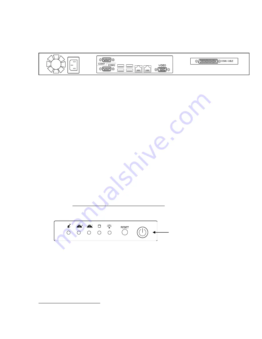
Connect peripherals
•
Connect the UPS data cable to the top left USB port (the one next to the COM2
designation) on the back of the system. Connect the other end of the data cable to
the UPS.
•
Connect the UPS to AC power. Turn on the UPS
•
Connect the VGA monitor to the
Video
connector on the back of the system.
•
Connect the keyboard cable to the bottom left USB port (the one next to the
COM2 serial port) on the back of the system.
•
Connect the mouse to the bottom right USB port (the one next to the NIC
outlined in grey) on the back of the system.
•
Connect the AC power cord of the monitor to the UPS and turn on the VGA
monitor.
•
The USB flash drive is already connected internally.
•
Connect the USB modem to the top right USB port on the back of the system.
Connect ether a dedicated POTS line or a PBX extension to the RJ-11 connector of
this modem.
Connect the system’s AC power cord to the row of UPS power outlets labeled
Battery
& Surge.
This will power up the server automatically.
If you need to shut the system down after connecting the power cord, use the power
button on the front to turn the system back on again
The InnLine IP application will start
2
. The system is ready to accept calls when you
see the screen in the following illustration.
2
Startup time may take several minutes.
Press this button
to power up the
system.