INSTALLATION
2.4
T1
BF-NGB2
F
2.4
2-2
2-2
2-2
2-2
2-2 FITTING THE DEMOUNTED P
FITTING THE DEMOUNTED P
FITTING THE DEMOUNTED P
FITTING THE DEMOUNTED P
FITTING THE DEMOUNTED PAR
AR
AR
AR
ARTS
TS
TS
TS
TS
For packing and transport reasons some machine parts are demounted.
The fitting of these parts requires proper equipment and 2 persons.
2-2.1
2-2.1
2-2.1
2-2.1
2-2.1 FITTING THE ADDITIONAL TABLES (
FITTING THE ADDITIONAL TABLES (
FITTING THE ADDITIONAL TABLES (
FITTING THE ADDITIONAL TABLES (
FITTING THE ADDITIONAL TABLES (
)))))
The additional tables are used for profiling and rabbeting also large pieces.
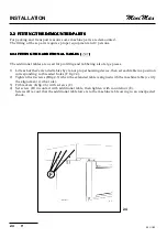
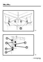
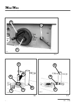
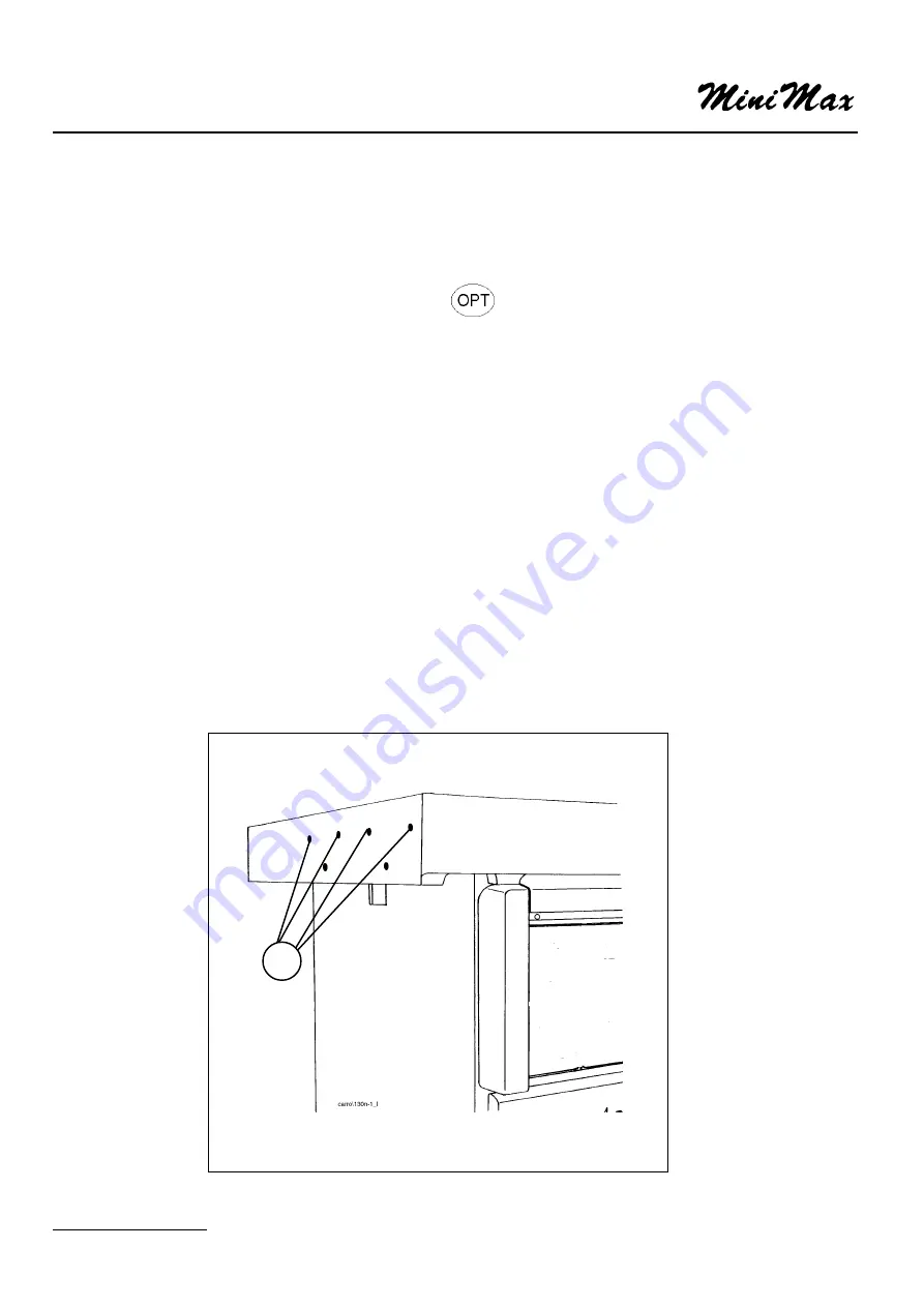
1) Lift each of the 2 extended tables by cran or proper hoisting device, then set each table in a position
corresponding to threaded holes (F fig.2.4).
2) Tighten the 4 screws (B fig.2.5) when the extended table is aligned with the machine table (verify
the alignement with a rule).
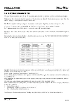
3) Fit brackets (K fig.2.6) with screws (C).
4) Set screw (D) in contact with additional table, then tighten with counternut (E).
Screws (D) avoid that the additional table lowers to the machine table owing to an unexpected
shock.
Summary of Contents for FORMULA T1
Page 22: ...T1 2 3 2 2 1 2 2 kg _____ 475 ...
Page 24: ...T1 2 5 2 2 6 2 5 B T13216 E D E K D C ...
Page 26: ...T1 2 7 2 MORSE1 L1 L2 L3 N PE P 2 7 ...
Page 29: ...INSTALLATION 2 10 T1 BF NGB2 ...
Page 32: ...T1 3 3 3 A1 A2 F L M A A1 A2 B A F B V V 3 1 P 3 2 ...
Page 34: ...T1 3 5 3 L H 3 4 A1 A2 F L M A A1 A2 B A F 3 4a ...
Page 35: ...MACHINE SETTING AND USE 3 6 T1 BF NGB3 ...
Page 38: ...T1 7 3 7 7 2 7 3 ALBE1 ALBE2 D B S A C B A Z T 7 1 A F P bf7 4 ...
Page 40: ...T1 7 5 7 B A 7 4 ...
Page 42: ...T1 7 7 7 7 6c 7 6a 7 6b ...
Page 44: ...T1 7 9 7 7 7 7 8 L S N C G P H ...
Page 46: ...T1 7 11 71 L H A M P C 7 9 ...
Page 48: ...T1 7 13 71 7 13 REGISTR M 7 12 H M P L I T F R ...
Page 50: ...T1 7 15 71 CUFFI4 F R 7 14 7 15 I T REGISTR M H M P L ...


