


REGOLAZIONI
7.10
T1
BF-NGB71
7-7
7-7
7-7
7-7
7-7 FITTING THE ADJUST
FITTING THE ADJUST
FITTING THE ADJUST
FITTING THE ADJUST
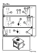
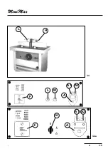
FITTING THE ADJUSTABLE HOOD-FENCE UNIT
ABLE HOOD-FENCE UNIT
ABLE HOOD-FENCE UNIT
ABLE HOOD-FENCE UNIT
ABLE HOOD-FENCE UNIT
Fitting
Fitting
Fitting
Fitting
Fitting
-
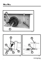
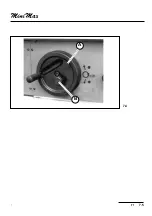
Rest the hood-fence unit on the worktable and fasten it by clamping handles (L and H fig.7.9).
-
By loosening handles (L and H) move the entire hood-fence unit to the position proper fot the
profiling depth required.
-
Then tighten handles.
Vertical pressers (A fig.7.9) ensure the constant pressure on the piece.
The guard for the hands supplied in the accessories bag is to be fitted into the holes on the top side
of fence halves (M and P fig.7.9).
A plate for the right use of the guard is applied on it.
Cover (C) of the spindle and tool hinders the ejection of chips or splinters which are sucked by the
proper hood.
IMPORTANT
IMPORTANT
IMPORTANT
IMPORTANT
IMPORTANT
:after adjusting turn the spindle to check if the tool touches the machine parts or the
guard.
Summary of Contents for FORMULA T1
Page 22: ...T1 2 3 2 2 1 2 2 kg _____ 475 ...
Page 24: ...T1 2 5 2 2 6 2 5 B T13216 E D E K D C ...
Page 26: ...T1 2 7 2 MORSE1 L1 L2 L3 N PE P 2 7 ...
Page 29: ...INSTALLATION 2 10 T1 BF NGB2 ...
Page 32: ...T1 3 3 3 A1 A2 F L M A A1 A2 B A F B V V 3 1 P 3 2 ...
Page 34: ...T1 3 5 3 L H 3 4 A1 A2 F L M A A1 A2 B A F 3 4a ...
Page 35: ...MACHINE SETTING AND USE 3 6 T1 BF NGB3 ...
Page 38: ...T1 7 3 7 7 2 7 3 ALBE1 ALBE2 D B S A C B A Z T 7 1 A F P bf7 4 ...
Page 40: ...T1 7 5 7 B A 7 4 ...
Page 42: ...T1 7 7 7 7 6c 7 6a 7 6b ...
Page 44: ...T1 7 9 7 7 7 7 8 L S N C G P H ...
Page 46: ...T1 7 11 71 L H A M P C 7 9 ...
Page 48: ...T1 7 13 71 7 13 REGISTR M 7 12 H M P L I T F R ...
Page 50: ...T1 7 15 71 CUFFI4 F R 7 14 7 15 I T REGISTR M H M P L ...


