


MOULDER FUNCTION
7.6
T1
BF-NGB7
7.6
7.5
veloc-1
7-4
7-4
7-4
7-4
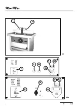
7-4 SPINDLE SPEED SELECTION
SPINDLE SPEED SELECTION
SPINDLE SPEED SELECTION
SPINDLE SPEED SELECTION
SPINDLE SPEED SELECTION
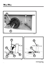
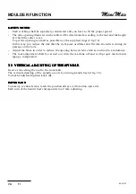
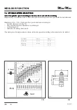
Select the spindle speed according to the tool, the wood and the working.
Select the spindle speed according to the tool, the wood and the working.
Select the spindle speed according to the tool, the wood and the working.
Select the spindle speed according to the tool, the wood and the working.
Select the spindle speed according to the tool, the wood and the working.
Diagram (fig.7.5) indicates how to select the speed according to the rim speed and the tool diameter.
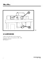
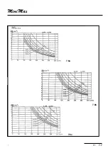
Diagrams (7.6a - 7.6b - 7.6cd) give the speed selection according to:
-
spindle diameter d1 (fig.7.6)
-
max. spindle length available for tool fitting l1
-
cutting heigth b
-
diameter of cutting element d2
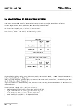
The table gives the approximate values of the rim speed according to the material to be milled.
MATERIAL
HSS m/s
HM m/s
Hard wood
50 / 70
50 / 70
Soft wood
42 / 60
45 / 70
Chipboard
50 / 70
Summary of Contents for FORMULA T1
Page 22: ...T1 2 3 2 2 1 2 2 kg _____ 475 ...
Page 24: ...T1 2 5 2 2 6 2 5 B T13216 E D E K D C ...
Page 26: ...T1 2 7 2 MORSE1 L1 L2 L3 N PE P 2 7 ...
Page 29: ...INSTALLATION 2 10 T1 BF NGB2 ...
Page 32: ...T1 3 3 3 A1 A2 F L M A A1 A2 B A F B V V 3 1 P 3 2 ...
Page 34: ...T1 3 5 3 L H 3 4 A1 A2 F L M A A1 A2 B A F 3 4a ...
Page 35: ...MACHINE SETTING AND USE 3 6 T1 BF NGB3 ...
Page 38: ...T1 7 3 7 7 2 7 3 ALBE1 ALBE2 D B S A C B A Z T 7 1 A F P bf7 4 ...
Page 40: ...T1 7 5 7 B A 7 4 ...
Page 42: ...T1 7 7 7 7 6c 7 6a 7 6b ...
Page 44: ...T1 7 9 7 7 7 7 8 L S N C G P H ...
Page 46: ...T1 7 11 71 L H A M P C 7 9 ...
Page 48: ...T1 7 13 71 7 13 REGISTR M 7 12 H M P L I T F R ...
Page 50: ...T1 7 15 71 CUFFI4 F R 7 14 7 15 I T REGISTR M H M P L ...


