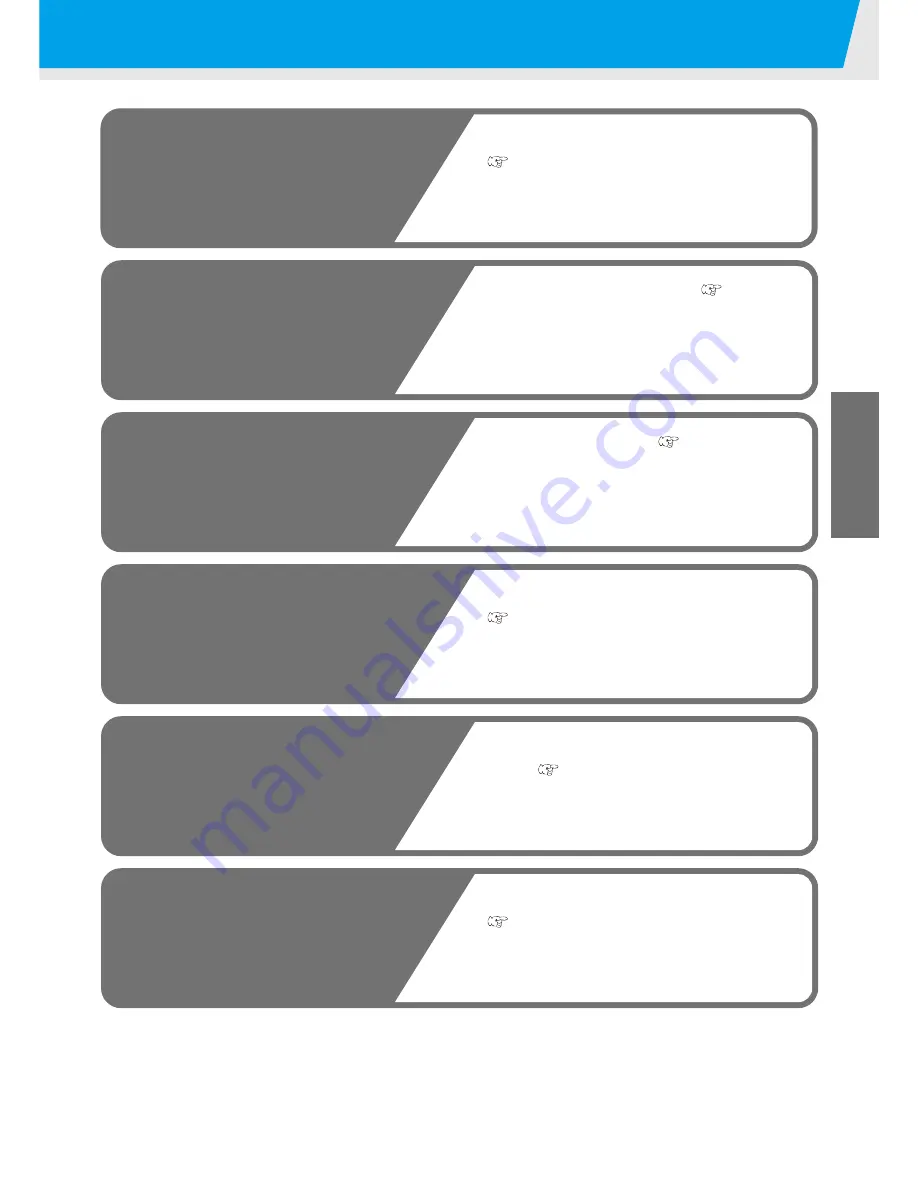
MIMAKI JF-1610 Operation Manual Download Page 35

2-3

2

Basic Operations

Operation flow

1

Turning the power ON

2

Setting the media

3

Test drawing

4

Execution of head 
cleaning

5

Drawing an image from 
source data

6

Turning the power OFF

See "Turning the power ON" 
(

P.2-4)

See "Setting the media" (

P.2-5)

See "Test drawing" (

P.2-9)

See "Execution of head cleaning"
(

P.2-10)

See "Drawing an image from source
data" (

P.2-12)

See "Turning the power OFF" 
(

P.2-15)

Summary of Contents for JF-1610

Page 1: ...D201645 20 MIMAKI ENGINEERING CO LTD TKB Gotenyama Building 5 9 41 Kitashinagawa Shinagawa ku Tokyo 141 0001 Japan Phone 81 3 5420 8671 Fax 81 3 5420 8687 URL http www mimaki co jp...

Page 2: ...and Function 1 3 Front Side 1 3 Rear Side 1 3 Operation Panel JF 1631 1 4 Operation Panel JF 1610 1 5 Carriage 1 6 Capping Station 1 6 Flushing BOX 1 6 EMERGENCY SWITCH 1 7 Connecting the cables 1 8 C...

Page 3: ...5 CHAPTER 3 Useful Function Changing origin 3 2 Changing origin with JOG keys 3 2 Changing origin with FUNCTION menu 3 3 Registering the thickness of the media 3 4 Register the thickness of the media...

Page 4: ...waste ink tank 4 10 Disposing of the ink in the wiper tank 4 11 Replacing the filter of the cooling fan 4 12 Cleaning nozzle face automatically 4 14 When media thickness is changed 4 15 Changing the i...

Page 5: ...zed 5 2 The device cannot perform printing 5 2 Display WATER NOT READY OR UV NOT READY 5 2 If image quality declines 5 3 Resolving nozzle clogging 5 3 Stopping the unit during the operation 5 3 Troubl...

Page 6: ...quipment is operated in a commercial environment This equipment generates uses and can radiate radio frequency energy and if not installed and used in accordance with the instruction manual may cause...

Page 7: ...alth for the U S Food and Drug Administration Implement regulations for laser products The sentence of This product complies with 21 CFR chapter I and subchapter J indicates compliance with the CDRH r...

Page 8: ...e putting the machine into service It is also necessary to keep this Operation Manual on hand Make arrangements to deliver this Operation Manual to the person in charge of the operation of this device...

Page 9: ...eed data receiving from a computer is allowed by using the high speed interface USB2 0 Curing fixation of ink after printing As the ultraviolet curing device UV lamp is mounted ink curing fixation of...

Page 10: ...n of the plotter The symbol indicates helpful information that will facilitate the use of the device Indicates the reference page for related contents The symbol indicates the case where some phenomen...

Page 11: ...this device falls into the category of UN No 3082 and UN Class 9 Since the ink is flammable never use fire when using the device When cleaning the ink station and head be sure to wear the supplied gog...

Page 12: ...e produces smoke or unpleasant smell fire or electric shocks can result Be sure to turn off the power switch immediately and detach the plug from the receptacle Check first to be sure that the device...

Page 13: ...it may cause pain in your eyes or visual impairment Be sure to wear safety glasses Do not apply ultraviolet UV light directly to your skin or it may cause irritation on your skin Be sure to use only t...

Page 14: ...waste cloth Entrust them to an industrial waste disposal contractor clarifying their contents Avoid ignition such as static electricity and impact spark Be sure to wear goggles and gloves for handlin...

Page 15: ...arning message is illegible or has come off purchase a new one from your local distributor or our office Refer to Appendix for the label Be sure to store the Anti freezing liquid in a cold and dark pl...

Page 16: ...se firing and or smoking Periodically clean the parts and measure the insulation resistance replacing deteriorated parts if any After the unit is used long time screws etc on the conductive parts may...

Page 17: ...A place that is not horizontal A place in which temperature and humidity vary by a great margin Use the device under the following environment Operating environment 15 30 35 65 Rh A place that vibrate...

Page 18: ...ad This Operation Manual This manual provides the explanation about the displayed characters and used keys on the Display Panel in addition to the operation procedures Proceed operations confirming th...

Page 19: ...e 1 6 Capping Station 1 6 Flushing BOX 1 6 EMERGENCY SWITCH 1 7 Connecting the cables 1 8 Connecting the USB2 0 interface cable 1 8 Connecting the power cable 1 8 UV irradiation device and Indicator 1...

Page 20: ...mm Approx 1150 kg JF 1610 3430 mm 2005 mm Min 1385 to Max 1465mm Approx 1050 kg This unit cannot be installed by the customer Its installation should be entrusted to our service personnel or your elec...

Page 21: ...and a display to display operation items are placed P 1 4 Power button This button is placed in the left side of the operation panel to turn ON OFF the power of this unit instead of the power switch...

Page 22: ...a is set BLOW Lamp P 2 12 Lit when media is removed from the table Key P 2 5 Switching VACUUM to BLOW and vice versa VACUUM BLOW key For switching a setting of VACUUM BLOW at rear side of the table RE...

Page 23: ...he vacuum ON OFF POWER Lamp Lit when the power is ON Key Press to start the test drawing P 2 9 TEST Key Press to start the head cleaning P 2 10 CLEANING Key Press to erase received data P 3 9 DATACLEA...

Page 24: ...Station The capping station on the front right side of the unit consists of the ink caps and suction nozzle used for the maintenance of the print head Flushing BOX A flushing BOX is placed in right an...

Page 25: ...n 1 7 1 Before Use EMERGENCY SWITCH One EMERGENCY switch is placed on the front face of the unit and 2 are placed on each of the buck surface and Y bar respectively When stopping the machine for safet...

Page 26: ...r ask a RIP maker near you or our branch office For supplying power to the device the power distribution board work is required Connecting the power cable cannot be installed by the customer Contact y...

Page 27: ...OTE MODE Blinking green REMOTE MODE at drawing OFF LOCAL MODE After cooling mode ON orange Drawing disabled UV lamp being cooled 5 minutes The UV lamp goes OFF in the following cases When operation fo...

Page 28: ...W 5 Clear SPC 0371CL Cleaning cartridge 1 1 To be used when changing the ink set or when the head is cleaned SPC 0371FS Display Color Display Color Display Color M Magenta c Light cyan S Spot color 1...

Page 29: ...six months If an extended period of time has passed after opening the cartridge drawing quality would be poor Store ink cartridges in a place that is out of the reach of children When discarding unus...

Page 30: ...m or palette so that it may warp downward Absorption of the media To maintain the absorption effect cover the suction holes not covered by the media with other media which is thinner than the media Th...

Page 31: ...ng the JOG keys 2 Executing Test drawing by pressing the key 3 Executing head cleaning by pressing the key 4 Execute setting of each function by pressing the key Function Mode Press the key during the...

Page 32: ...1 14...

Page 33: ...Setting the media on JF 1610 2 5 Setting the media on JF 1631 2 6 Using of Roll Sheet 2 8 Test drawing 2 9 Execution of test drawing 2 9 Execution of head cleaning 2 10 When cleaning with Normal or Ha...

Page 34: ...image 1 Close the door 2 Perform drawing while keeping the door closed When setting the media avoid contact of the media to the door The door could be closed by vibration Close the door slowly so tha...

Page 35: ...wing 4 Execution of head cleaning 5 Drawing an image from source data 6 Turning the power OFF See Turning the power ON P 2 4 See Setting the media P 2 5 See Test drawing P 2 9 See Execution of head cl...

Page 36: ...his unit When the power is switched on the LCD displays the firmware version number Initial operation is started 2 Local Mode starts 3 Turn the power of connected computer ON When the power is turned...

Page 37: ...e as shown in the figure on the right When you want to change the point of origin please refer to P 3 2 If within the absorption area there are suction holes not closed by the media close such suction...

Page 38: ...ed when it is turned horizontally 2 Pressing the key put on the VACUUM lamp 3 Pressing the or keys absorb the media to the table key Turns ON OFF the vacuum of the absorption area starting with F key...

Page 39: ...e refer to P 3 2 Media size Suction valve Vacuum setting F1 F2 F3 F4 R1 R2 FRONT REAR 3 x 6 Board Open Open Open Open Close Close ON OFF 4 x 8 Board Open Open Open Open Open Close ON ON 5 x 10 Board O...

Page 40: ...Setting the media 2 8 Using of Roll Sheet Set the roll sheet on the roll sheet hunger on the back face of this device...

Page 41: ...nish the operation When the result is abnormal execute head cleaning P 2 10 Printing is disabled when the following messages are displayed It is enabled when the message has disappeared WATER NOT READ...

Page 42: ...l normal result is obtained normal To be used if ten odd numbers of the lines are missing when the test pattern is made Suction and wiping with the cap will be performed P 2 10 wiping To be used if se...

Page 43: ...s the key The cleaning will be started When the cleaning is completed the system is turned to the local mode 7 Execute test drawing and check the result of the test drawing Repeat cleaning and test dr...

Page 44: ...W lamp 2 Evacuation of Y bar from the table P 2 14 to evacuate the Y bar out of the table 3 Remove the media If the UV irradiation device is not ready or the temperature of the water heating system ha...

Page 45: ...3 Press the key Received data is erased and the device returns to the local mode Move the Y bar When you wish to check the drawing results etc you can move the Y bar Set the evacuation position view...

Page 46: ...ng the origin of the drawing 6 Press the key The value is set and the screen returns to Step 2 Evacuation of Y bar from the table Used for evacuating the Y bar from the table for checking a drawing re...

Page 47: ...cut the power Execute the cool down operation when UV lamp is on The power is cut automatically when the cool down operation is completed When this device is not used for a long time execute the foll...

Page 48: ...2 16...

Page 49: ...gap 3 6 Adjust head gap with the or keys 3 6 Registering Head gap value 3 7 Turing the UV lamp off 3 8 Other useful functions 3 9 Data clear 3 9 Displaying information of this device 3 9 Each setting...

Page 50: ...ght pointer mark by pressing the keys Move the light pointer mark to the position to set a new origin 3 Press the key when the drawing origin is determined The origin is changed The setting value for...

Page 51: ...in the parentheses indicates the distance from the origin to the maximum effective area 5 Press the key 6 Select the Y OFFSET by pressing the or keys 7 Press the key 8 Input value by pressing the or...

Page 52: ...ress the key in the local mode 2 Select the HEAD HEIGHT by pressing the or key 3 Press the key 4 Press the key 5 Press the or key to enter the thickness of loading media Set value 0 0 to 50 0mm 6 Pres...

Page 53: ...ress the key The media thickness will be measured automatically The measured thickness will be displayed The carriage will move to the evacuation position and the screen returns to the one displayed i...

Page 54: ...thod of selecting with keys and a method of setting in the HEADGAP of the FUNCTION menu Adjust head gap with the or keys 1 Press the or key 2 Adjust with pressing the or key 3 Press the key UP DOWN OR...

Page 55: ...5 Press the key 6 Input the head gap value by pressing the or key Set value 1 0 to 5 0mm 7 Press the key 8 Press the key to finish If a correct value is not set to the head gap value the print qualit...

Page 56: ...the UV LAMP OFF by pressing the or key 3 Press the key 4 Press the key Turning off operation of the UV lamp is started Drawing is disabled When turning off operation completes indication in the right...

Page 57: ...formation Command information Irradiation time of the UV lamp Remaining amount of ink 3 Press the key to return to the local mode Information on your machine type can be confirmed in P 3 16 Displaying...

Page 58: ...item to be set by pressing the or key As for setting items see the next page 7 Press the key 8 Select a value by pressing the or key As for setting values see the next page 9 Press the key 10 Press th...

Page 59: ...onducted in both directions when the head moves on the media at drawing Quicker drawing compared to UNI DIRN UNI DIR Drawing is conducted in one direction when the head moves on the media at drawing H...

Page 60: ...The UV lamp is lit with 100 of its light intensity STANDARD The UV lamp is lit with 60 of its light intensity LOW The UV lamp is lit with 40 of its light intensity NONE The UV lamp is not lit while d...

Page 61: ...g the or key 5 Press the key Drawing type setting screen is displayed 6 Select the HOST or the PLOT by pressing the or key HOST Setting of the computer has the priority PLOT Setting of this device has...

Page 62: ...lect the DISPLAY by pressing the or key 3 Press the key 4 Select a language by pressing the or key Default is English 5 Press the key 6 Press the key to finish Set value remains after cutting the powe...

Page 63: ...n the local mode 3 Select the MAINTENANCE by pressing the or key 4 Press the key 5 Select the LIST by pressing the or key 6 Press the key Output of the setting list starts 7 Press the key to finish Se...

Page 64: ...essing the or key and press the key The following 2 information can be displayed FW version of this device Serial No 7 Press the key three times to finish F UNCT I ON V I EW EN T FUNCTION F UNCT I ON...

Page 65: ...Set the number of times for over painting Finer drawing can be obtained by conducting the over painting REFRESH Level 0 to 3 Set the refreshing revel for preventing the head from clogging in a dusty...

Page 66: ...pressing the or key 5 Press the key 6 Press the key Resetting the setup 7 Press the key twice to finish In the SETUP RESET resetting is allowed only on contents changed in the SETTING ITEM F UNCT I O...

Page 67: ...using those holes For JF 1610 the guide holes are not arranged in the front side Arrangement of guide holes When you prepare the guide for setting the media please use the following sizes as reference...

Page 68: ...3 20...

Page 69: ...ling fan 4 12 Cleaning nozzle face automatically 4 14 When media thickness is changed 4 15 Changing the ink set 4 17 Changing the ink set 4 18 In case defective printing is not resolved 4 20 Filling t...

Page 70: ...ock hazards and breakage of the device Prevent moisture from entering inside device If the inner part of the device becomes wet electric shock hazards and breakage of the device can result Conduct mai...

Page 71: ...Daily Maintenance Maintenance of frame component If the frame components of the device have stained dampen a poece of soft cloth with water or neutral detergent diluted with water squeeze it and wipe...

Page 72: ...ridge turning up a side containing the IC chip Ink fill up starts Display on the screen Outline Remaining amount of ink in an ink cartridge is few Drawing can be continued but running out of ink may o...

Page 73: ...e 3 Press the key again The menu will return to the LOCAL mode auto matically when no trouble exists If two or more cartridges have a problem press the key again to display the second cartridge When a...

Page 74: ...the flushing BOX on the right side Contents of the cleaning kit Maintenance cleaning liquid SPC 0385 Gloves Paper towel Goggles When conducting the replacing be sure to wear the supplied goggle and g...

Page 75: ...Cleaning flushing BOX 4 7 4 Daily Maintenance 5 eplace the absorption material inside the flushing BOX 6 Replace the absorption material inside the flushing BOX on the left side...

Page 76: ...face of the carriage periodically 1 Turn on the power After the initial movement the system turns to the local mode 2 Remove the cover on the right side of the Y bar 3 Open the front cover 4 Remove t...

Page 77: ...ion where the right side flushing BOX was 11 Instill the cleaning liquid to the swab and clean the side of the head Avoid wiping the nozzle surface of the head It would cause the nozzle clogging In ca...

Page 78: ...loor To prevent the floor from being stained with ink Dispose the waste ink pursuant to the regulations of your district 4 Set the empty waste ink tank Close the waste ink box cover To avoid hurt hand...

Page 79: ...cover 1 Remove the screws fixing the both sides of the waste ink BOX cover 2 Open the cover 2 Remove the wiper tank and discard the waste ink Discard the waste ink pursuant to your local regulations...

Page 80: ...cover and remove the cover 4 Remove the filter Assy Take out the finger screws on the upper part of the cooling fan and remove the filter Assy When replacing be sure to wear the supplied goggles and g...

Page 81: ...y 6 Replace the filtering element Prepare the new filtering element and replace with it 7 Return the filter Assy to the original state 8 Attach the filter Assy to the cooling fan and tighten the screw...

Page 82: ...Select the INT WIPING by pressing the or key 4 Press the key 2 Set the number of scanning times OFF 0 255 by pressing the or key Periodical wiping is not executed when the number is set to 0 3 Press...

Page 83: ...ct the PRN adjust MODE of the maintenance menu 1 Press the key in the local mode 2 Select the MAINTENANCE by pressing or key and press the key 3 Select the PRN adjust by pressing or key 4 Press the ke...

Page 84: ...e is formed at the point 140 8 Adjust it by pressing or Setting value 0 to 400 When there is no pattern forming a straight line between 0 and 400 1 Once again perform the checking of the head gap P 3...

Page 85: ...Yellow K Black m Light magenta c Light cyan S Special color 1 s Special color 2 M Magenta C Cyan Y Yellow K Black m Light magenta c Light cyan W White Cl Clear coat M Magenta C Cyan Y Yellow K Black...

Page 86: ...For the 6 colors ink set Refer to P 4 17 Available Ink Sets when the ink set is selected Light cyan Lc and Light magenta are indicated as c and m respectively 3 Press the key 4 Press the key 5 Remove...

Page 87: ...Maintenance 8 Set the ink color cartridge indicated on the display when the display shown on the right is indicated 9 Press the key Ink charging starts It returns to the local mode after charging I NK...

Page 88: ...NK with pressing the or key 6 Press the key 7 Select the ink filling for each head 1 Move the cursor with or keys 2 Select ink filling with or keys Select ink filling for all the heads Fill The ink ca...

Page 89: ...illing of the ink will start When the ink filling is completed the screen as shown in the right will be displayed If you press the key twice the system will return to the local mode When replacing the...

Page 90: ...Press the key REMOVE CARTRIDGE is displayed on the screen 2 Pull out the white ink cartridge form the ink station 3 Press the key White ink discharge operation starts 4 Shake the white ink cartridge u...

Page 91: ...on As shown in the drawing set an ink cartridge turning up a side containing the IC chip 6 Press the key Ink filling starts A message shown in the right is displayed after completion of white ink fill...

Page 92: ...or keys 2 Select execution release of maintenance function pressing or keys If the head maintenance function is released the display will show When you do not wish to use the head maintenance functio...

Page 93: ...rawn 1 Select the SP REFRESH MODE of the maintenance menu 1 Press the key in the local mode 2 Select the MAINTENANCE by pressing or key and press the key 3 Select the SP REFRESH by pressing or key 4 P...

Page 94: ...e or key and press the key 3 Press the key again 4 Press the key The carriage moves to the location near the flushing BOX on the right side The wiper will move toward you and the shutter of the cap wi...

Page 95: ...e dust or fiber after use such as paper towel When remarkable deformation or wear is seen on the wiper M replace it with the new one 9 Check the inside of the suction nozzle and clean them if they are...

Page 96: ...out by around 0 5 mm after being attached 13 Wipe off the ink and others stuck to the cap with nonwoven cloth Avoid using the material that will leave dust or fiber after use such as paper towel 14 W...

Page 97: ...water mixed with antifreeze liquid pursuant to the regulations of your district Be sure to wear goggle and gloves for handling the antifreeze liquid Use the recommended antifreeze liquid by Mimaki Ant...

Page 98: ...mode on the maintenance menu Refer to the bottom of this page The antifreeze liquid mixed water inside the piping can also be discharged completely Further this work is performed safely as it may be d...

Page 99: ...remaining in the system starts When discharging is completed a message shown in the right is displayed 10 Take out the hot water tank again Take out with referring to the procedure 3 6 11 Move antifr...

Page 100: ...g the screws 4 pieces fixing both sides of the water heater device 3 Remove the catch clips 4 Holing up the water heater device and hang the hanger to the hook 5 Take out the water heater tank Transfe...

Page 101: ...ions When the exhaust blower does not function normally ERROR706 UV1 overheat will be displayed frequently 1 Put off the UV lamp and turn OFF the power 2 Remove the front right cover and the front lef...

Page 102: ...out the exhaust blower 7 Fix the new exhaust blower Tighten the screws 2 pieces to fix the exhaust blower 8 Return the exhaust blower Assy to the original state 1 Fix the exhaust blower connecting ca...

Page 103: ...the operation of P XX when OFF of the UV lamp is required If OFF is selected go to Procedure 5 if ON is selected go to procedure 8 5 Press the key 6 Set the time duration to turn off the UV lamp after...

Page 104: ...ver When cleaning be sure to wear the supplied goggles and gloves since you may get ink in your eyes Wear gloves not to injure your hands at cleaning of the UV lamp filter The replacement of the UV la...

Page 105: ...ean the mesh filter Lay a paper towel and remove the stains on the mesh filter spraying alcohol When it is hard to remove the stains soak the paper towel with alcohol and press it lightly Do not brush...

Page 106: ...ight Press the key to return to the local mode Replacing UV lamp When the irradiation duration has exceeded the predetermined period of time a message to urge replacement of UV lamp is displayed When...

Page 107: ...wrench 2 Pull off the UV lamp cassette 6 Place a new UV lamp Fix the bolt on the front of the UV lamp cassette using supplied hexagonal wrench 7 Fix the exhaust blower Assy and tighten the finger scre...

Page 108: ...LAMP by pressing the or key 4 Press the key 2 Select LAMP TIMER by pressing the or key 3 Press the key 4 Select a UV lamp to be reset by pressing the or key CH1 CH2 ALL Reset irradiation duration of...

Page 109: ...key 6 Select resolution by pressing the or key Setting value 300 x 300 dpi 300 x 600 dpi 600 x 600 dpi 600 x 1200 dpi 900 x 600 dpi 900 x 1200 dpi 1200 x 1200 dpi 7 Press the key 8 Select drawing qual...

Page 110: ...Light intensity becomes stronger 3 Press the key 4 Press the key twice to finish 5 Check UV curing again Set media and create the drawing pattern of the UV light intensity P 4 41 If preparation of the...

Page 111: ...cking the illumination intensity is displayed on the operation panel Check the UV lamp illumination intensity following this operation manual and use it as a reference when replacing the UV lamp Notes...

Page 112: ...e to press the sensor part Do not pull the code 3 Turn the bracket to the obverse side and adjust the sensor hole to the center of the bracket hole 2 Select UV lamp mode from the maintenance menu 1 Pr...

Page 113: ...it using two guide holes located on the backmost part 4 Operate the switch of the illumination meter 1 Turn the switch of the illumination meter to H 2 Press the button of the left side several times...

Page 114: ...ation time does not exceed 500 hours when the illumination intensity decreases rapidly the UV lamp unit may be broken Contact a nearby sales agency or our business office You can check the hardening s...

Page 115: ...e device cannot be energized 5 2 The device cannot perform printing 5 2 Display WATER NOT READY OR UV NOT READY 5 2 If image quality declines 5 3 Resolving nozzle clogging 5 3 Stopping the unit during...

Page 116: ...EADY appears on the display the water temperature in the water heater has not reached the predetermined value If UV NOT READY is displayed as the UV lamp has not been ready the UV lamp can not be used...

Page 117: ...Press the EMERGENCY SWITCH for stopping the unit urgently for the safety reason One EMERGENCY switch is placed on the front face of the unit and 2 are placed on each of the back surface and Y bar res...

Page 118: ...layed after this operation call the dealer or our branch for the service The ink will expire soon or has expired Replace the ink cartridge of which color is shown on the LCD with a new one P 4 4 The t...

Page 119: ...it on after a while If the same error message appears again on the LCD contact your local distributor to call for service Head setting failure Control circuit board is defective The device has receive...

Page 120: ...rtridge is not attached to the ink station Attach the ink cartridge s correspond ing with the color shown on the dis play P 4 20 Waste ink tank is full Remove the waste ink tank and set an empty waste...

Page 121: ...UV lamp in the left side of the unit An error occurs on the interface between the I F board and the control board Perform a proper operation Head is not selected Select a head to be cleaned or filled...

Page 122: ...is not filled up Execute ink filling P 2 4 Changing time for the UV lamp Contact your local distributer or to call for service to change the UV lamp Occurrence of media jam Press the key to elevate th...

Page 123: ...specifications and functions of this unit are described Specifications 6 2 Basic unit specifications 6 2 Specifications for ink 6 3 Position of the warning label 6 4 Function Flowchart 6 7 CHAPTER 6...

Page 124: ...ducibility 0 2 mm Perpendicularity 0 5 mm 500mm Head gap adjustment Automatic head adjustment enabled Media absorption Blower vacuum absorption UV unit UV irradiation unit and UV power installed Waste...

Page 125: ...acity of ink cartridge 440CC Shelf life One year from the date of manufacture Storage temperature During storage 15 to 35 During shipping 0 to 60 within 2 weeks permitted The ink freezes up if it is l...

Page 126: ...el Be sure to fully understand the warning given on the labels In the case where any of the warning label has become so soiled that the warning message is illegible or has come off purchase a new one...

Page 127: ...5 6 Appendix No Reorder No Lavel No Reorder No Lavel 1 M903330 2 M903763 3 M903747 4 M904131 5 M904148 6 M903764 7 LHCM 02 8 PEC 02 9 M904130 10 M902396 11 M963239 12 M905491 13 M905490 14 M901549 15...

Page 128: ...6 6...

Page 129: ...EANING key ON OFF COLOR SELECT hard wiping CL EAN I NG TYPE n o r ma l CL EAN I NG HEAD MCYKKYCM CL EAN I NG DATA CLEAR key LOCA L 2 5mm DATA CL EAR DATA CL EAR ENT Displaying the guidance infomation...

Page 130: ...V I EW START e n t HEAD HE I GHT MED I A TH I CKNESS e n t HEAD HE I GHT TH I CKNESS CHECK e n t OR I G I N SE L ECT X OF FSET V I EW SET V I EW POS e n t HEAD HE I GHT HEAD GAP e n t FUNCT I ON OR I...

Page 131: ...CHECK CHECK START e n t TH I CKNESS CHECK MOV I NG NOW HEAD GAP P L EASE WA I T V I EW POS I T I ON MM TH I CKNESS CHECK CHECK I NG 1 0 to 5 0 0 to 50 0 9999 to 9999 STANDARD FINE FAST BI D UNI D UNI...

Page 132: ...be followed SET UP REFRESH e n t SET UP I NK L AYERS e n t SET UP UV L EVE L e n t SET UP PR I OR I TY e n t SET UP MM I NCH e n t SET UP UV SCAN ADD e n t SET UP SETUP RESET e n t FUNCT I ON MA I NT...

Page 133: ...0 to LEVEL 3 SET UP WA I T I NG e n t SET UP WA I T I NG L EVE L 1 LEVEL 0 to LEVEL 3 SET UP DRAWI NG e n t SET UP DRAWI NG L EVE L 1 SET UP I N I T I A L I ZE OK e n t SET UP UV SCAN ADD 0 ON OFF ST...

Page 134: ...e followed To be followed MA I NTENANCE I NT WI P I NG e n t MA I NTENANCE WH I TE MANT e n t MA I NTENANCE PRN a d j u s t e n t MA I NTENANCE I NKSET e n t MA I NTENANCE F I L L UP I NK e n t MA I N...

Page 135: ...MOVE CARTR I DGE I NKSET SET UP OK e n t I NKSET MCYKmcWS WASH I NG P L EASE WA I T I NKSET WS SET CL EAN TOOL WASH I NG P L EASE WA I T I NKSET WS SET CARTR I DGE WASH I NG P L EASE WA I T I NKSET WS...

Page 136: ...6 14 Followed Followed To be followed To be followed MA I NTENANCE SP REFRESH e n t MA I NTENANCE UV L AMP e n t MA I NTENANCE WATER CHNG e n t...

Page 137: ...G L EVE L CHECK SET THE TOOL e n t L EVE L CHECK CHANNE L CH1 L EVE L CHECK UV L EVE L H I GH L EVE L CHECK CHECK START e n t L EVE L CHECK MOV I NG L EVE L CHECK CHK THE TOOL e n t L EVE L CHECK SE L...

Page 138: ...MA I NTENANCE I NFOMAT I ON e n t MA I NTENANCE L I ST e n t MA I NTENANCE WA I T CAP e n t FUNCT I ON UV L AMP OF F ENT UV L AMP OF F START e n t FUNCT I ON D I SP L AY ENT D I SP L AY E n g l i s h...

Page 139: ...ENANCE VERS I ON e n t MA I NTENANCE MA I N V e r 1 0 0 MA I NTENANCE SE L I A L No e n t MA I NTENANCE S N 0 0 0 0 0 0 0 0 MA I NTENANCE PR I NT I NG MA I NTENANCE CAPP I NG OF F MA I NTENANCE P L EA...

Page 140: ...6 18...

Page 141: ...D201645 20 29082008...

Page 142: ...NH FW 2 80 Printed in Japan MIMAKI ENGINEERING CO LTD 2008...

Reviews: