


MICRONOR AG
MR340-1 DIN Rail Module Controller
Page 22 of 74
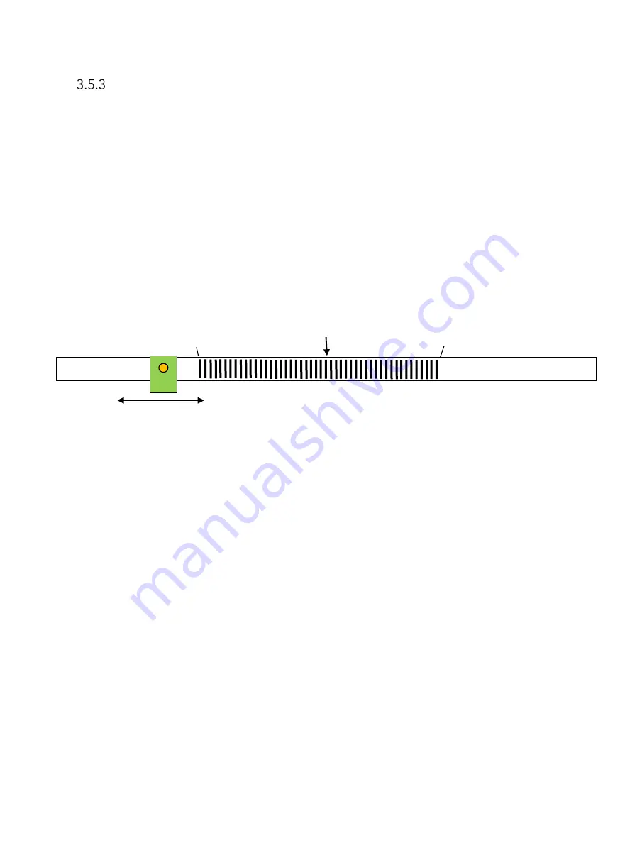
Indexing for Linear Absolute Position
The MR343 linear sensor system is an incremental encoder and will not know the absolute
position when the unit is powered up. Generally, an index point must be provided to obtain
absolute position.
Since the MR343 fiber optic sensor works different from standard encoders, it is possible to
reserve a “homing” area on the film strip. Outside the actual work area, the film is left
transparent without alternating lines.
After the robot powers up, the servo system must drive the sensor head either left or right to
the clear “homing” area until encoder pulses are no longer received. Tthe desired Preset
reference count, corresponding to the absolute known position to the start of the first line, is
loaded into the position counter. The servo motor then drives towards the start of the working
area. The position counter will start counting as soon as the first line is encountered.
Note: The number examples above are when x2 multiplier is used.
The left and right homing positions are provided to the servo control system as part of an
initial factory calibration cycle.
Whenever there is opportunity to position the sensor to an area outside the working area and
perform a “homing” procedure, the above described scheme is elegant and does not add
complexity or cost to the system.
This procedure can also be combined with an optical input sensitivity calibration sequence
per Section 3.6.
Left Home
Position -382
Right Home
Po382
Working Area
Center Position = 0
Pick-Up
-382, -381, -380
+380, +381, +382


