


MICRONOR AG
MR340-1 DIN Rail Module Controller
Page 14 of 74
3.4
Electrical Connections To Controller
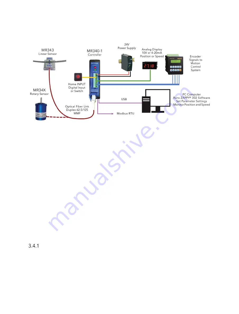
Figure 10. Typical MR340 Encoder Sensor System connections to Motion Control System
The MR340-1 controller requires a 24V DC power supply delivering a minimum of 100mA
current. The Fiber Optic Sensor shall be connected via the Duplex LC Fiber Optic cable. Fiber
Optic extension cables interconnected via Duplex LC mating adapters may also be used.
Connections from the controller to the users equipment depends on the application. For a
motor drive controlling the speed, the quadrature signals must be connected to the encoder
inputs of the motor drive. The user can configure the differential outputs to provide 5V, 12V or
24V signal levels. The factory setting is 5V. (Consult section 8.1 User Parameter Settings)
If the sensor system is used to display position or speed, an analog panel meter may be
connected to the analog signal output (SIG+/SIG-). The output can be programmed for either
Voltage (±10V) or current (4-20mA) as well as freely scaled to indicate either position or
speed. (Consult section 8.1 User Parameter Settings)
An external HOMING Input is available to connect a “Homing Switch” allowing the system to
calibrate to an absolute position at start-up. This input offers additional functionality. Consult
Section 3.7.2 for additional information.
Main Electrical Connections
The unit is powered by 24 VDC with maximum 100mA current consumption.
Encoder output levels are User Selectable via Zappy® 302: 5V, 12V or 24V
Serial Interface is Modbus RS485/RS422 compatible.
Default baud-rate 57600, 8bit, 1 stop, no parity
Default address 235


