


18
9.
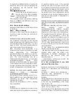
Hydraulic schemes
The presented hydraulic schemes does not replace central heating engineering design
and may be used for information purposes only!
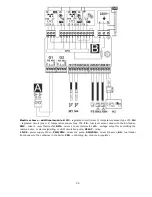
Diagram with 4-way control valve for central heating circuit, where: 1 – boiler, 2 – controller, 3 -
water temperature sensor returning to the boiler CT4, 4 – boiler temperature sensor CT4, 5 – exhaust
temperature sensor CT2S (temperature monitoring only), 6 – 4-way valve servo, 7 – mixer circuit pump, 8 –
mixer circuit temperature sensor CT4, 9 – HUW container, 10 – HUW pump, 11 – HUW sensor CT4, 12 – out-
door temperature (weather) sensor CT6-P, 13 – ecoSTER TOUCH room control panel or standard room
thermostat, 14 – thermal isolation.
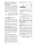
In order for the valve (6) to be able to effectively increase the return water temperature,
set a high set temperature of the boiler. In order to improve the water circulation in natural
systems (highlighted circuit in the figure): use large nominal diameter pipes and four-way
valve, avoid unnecessary angles and reductions, maintain a min. 2° horizontal pipe slope,
etc. If the sensor (3) is attached to the pipe, isolate it with foam surrounding the pipe and
sensor.
RECOMMENDED SETTINGS:
Parameter
Setting
MENU
Preset boiler temperature
75-80
C
menu
Boiler settings
Min. preset boiler temperature
65
C
menu
Service settings
Boiler settings
Increasing of preset boiler temp.
5-20
C
menu
Service settings
CH and HUW settings
Mixer 1 support
CH ON
menu
Service settings
Mixer 1 settings
Maxer 1 preset temperature
70
C
menu
Service settings
Mixer 1 settings
Mixer 1 heating curve
0.8 – 1.4
menu
Mixer 1 settings
Mixer 1 weather control
ON
menu
Mixer 1 settings
Mixer 1 thermostat selection
ecoSTER T1
menu
Service settings
Mixer 1 settings
Summary of Contents for ecoMAX 860P
Page 6: ......
Page 7: ...INSTRUCTION MANUAL ecoMAX 860P...
Page 16: ...16...
Page 17: ...17 INSTALLATION AND SERVICE SETTINGS ecoMAX 860P...
Page 44: ...44...
Page 45: ......
Page 46: ......
Page 47: ......


