


23
inside the casing of the regulator marked with
.
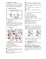
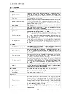
Before making any connections remove the
cover from the casing of the regulator as
shown below.
cables secured from splitting should be
connected to screw terminals of the (6)
connector.
cables should be put through cable outlets
in the casing (1) and secured from ripping
or loosening by a holdfast (5 – break it out
from the casing).
cables insulation should be stripped by the
minimum possible, max. 60mm. If there is
a necessity to strip cable insulation more
than 60mm, cable leads should be fasten
together or with other leads near the
connector – in order to prevent contact
with unsafe parts in the case of falling out
the lead from the connector.
it is not allowed to coil excess of the cable
and to leave not connected leads inside
the casing of the regulator.
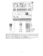
1 – cable outlets, 2 – holdfasts placing (should be
broken out for the casing), 3 – improper cable
connection (it is not allowed to coil excess of the
cable inside the device and to leave cables with
stripped insulation), 4 – proper cable connection, 5
– holdfast of the cable, 6 – connector.
Electrical cables should be isolated
from hot parts of the boiler,
especially from flues.
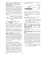
When the cables connection is done the
cover of the connectors has to be put in
place.
The connectors cover should be
always screwed on to the casing of
the regulator. Apart from providing
safety for the user, the connectors
cover also protects the interior of
the regulator from hazardous
environmental conditions providing
a proper level of the IP protection.
Summary of Contents for ecoMAX 860P
Page 6: ......
Page 7: ...INSTRUCTION MANUAL ecoMAX 860P...
Page 16: ...16...
Page 17: ...17 INSTALLATION AND SERVICE SETTINGS ecoMAX 860P...
Page 44: ...44...
Page 45: ......
Page 46: ......
Page 47: ......


