Metal-Fach ecoMAX 860P User'S Manual And Installation Download Page 26

26 


12.6


Temperature sensors connection 

The regulator is compatible only with CT4 and 
CT2S  sensors.  The  use  of  other  sensors  is 
prohibited!. 
Wires  of  sensors  can  be  extended  by  wires 
with diameter no smaller than 0,5mm

2

. Total 

length  of  wires  in  each  sensor  should  not 
exceed 15m.   
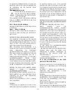
The  boiler  temperature  sensor  should  be 
installed in a thermostatic pipe installed in  the 
boiler.  Temperature  sensor  of  hot  water  silo 
should  be  installed  in  a  thermostatic  pipe 
welded  into  the  silo.  The  mixer  temperature 
sensor should be installed in a sleeve located 
in stream of running water in pipe, but also it 
can be installed on the pipe, on condition that 
it is thermally isolated from the pipe. 


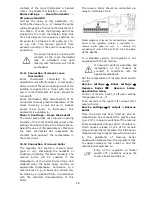
Mounting temperature sensor: 1 - pipe, 2 – clamps, 
3 - thermal insulation, 4 -  temperature sensor. 


Sensor  must  be  protected  from 
getting loose from the surfaces to 
which they are connected. 

Good  thermal  contact  should  be  maintained 
between  sensors  and  the  measured  surface. 
To  this  purpose  thermal  grease  should  be 
used. It is not acceptable to lubricate sensors 
with water or oil. Wires of sensors should be 
separated  from  network  electrical  wires.  In 
such  a  case  wrong  readings  of  temperature 
may  be  shown.  Minimum  length  between 
those  wires  should  be  10  cm.  It  is  not 
acceptable to allow for contact between wires 
of sensors and hot parts of the boiler and the  
heating  installation.  Wires  of  sensors  are 
resistant  to  temperature  not  exceeding 
100°C.  

12.7


Weather sensors connection  

The  regulator  cooperates  solely  with  the 
weather sensor type CT6-P. The sensor should 
be installed on the coolest wall of the building. 
Usually it is the northern wall, under the roof. 

The  sensor  should  not  be  exposed  to  direct 
sunrays  and  rain.  The  sensor  should  be 
installed  at  least  2  m  above  the  ground,  far 
away  from  windows,  chimneys  and  other 
sources of heat.  
To  make  the  connection  use  wire  with 
diameter  at  least  0,5mm2  up  to  25m  long. 
Polarization of wires is not essential. Second 
end should be connected to terminals of the 
regulator  or  properly  to  the  used  kind  of 
regulator. 
The sensor should be screw to the wall. Access 
to assembly holes is possible after unscrewing 
the cover of the sensor. 


12.8


Connecting exhaust sensor 

The  exhaust  sensor  should  be  fitted  in  the 
boiler flue. The gap between the sensor and 
the flue should be sealed. The sensor should 
be  installed  by  a  qualified  fitter,  while 
observing  regulations  applicable  for  chimney 
systems.  The  emission  sensor  should  be 
connected to the sensor terminals acc. to The 
emission  sensor  lead  cannot  touch  hot 
elements  of  the  boiler  and  the  flue,  the 
temperature  of  which  exceeds  350°C.  The 
emission  sensor  should  be  installed  in  such 
distance  from  the  boiler  at  which  it  is  not 
directly  exposed  to  flames,  and  where  the 
emission temperature does not exceed 450°C. 

Summary of Contents for ecoMAX 860P

Page 1: ...room panel ecoSTER200 and internet module ecoNET300 are not part of standard equipment regulator USER MANUAL AND INSTALLATION ISSUE 1 1 APPLIES TO SOFTWARE MODULE PANEL v 01 XX XX v 01 XX XX 02 2017 e...

Page 2: ...ed to water PRINCIPLES INDIVIDUAL FUZZY LOGIC The regulator must be programmed individually for the given type of boiler and fuel It is inadmissible to change the type of gear motor fan and to make ot...

Page 3: ...WEATHER SENSORS CONNECTION 26 12 8 CONNECTING EXHAUST SENSOR 26 12 9 CHECKING TEMPERATURE SENSORS 27 12 10 CONNECTION OF BOILER ROOM THERMOSTAT 27 12 11 CONNECTION OF MIXER S ROOM THERMOSTAT 28 12 12...

Page 4: ...for boiler manufacturers Before applying the regulator a boiler manufacturer should check if the regulator s mating with the given boiler type is proper and whether it can cause danger The regulator...

Page 5: ...al is a supplement for the boiler manual In particular except for this manual the boiler manual should also be observed The regulator manual is divided into two parts for user and fitter Yet both part...

Page 6: ......

Page 7: ...INSTRUCTION MANUAL ecoMAX 860P...

Page 8: ...dule Night time decrease boiler On No Yes Reduction value Schedule HUW settings HUW preset temperature HUW pump mode Off Priority No priority HUW container hysteresis HUW disinfection Night time decre...

Page 9: ...increase from mixer circulation increasing preset temperature for loading buffer warning HUW disinfection mode is active 4 way valve partially closed active return protection 5 fan operation symbol 6...

Page 10: ...itionally adjusted with individual fuel feeding times and fan speeds affecting the actual output of the boiler The output level parameters are accessible through the menu Boiler Settings Output modula...

Page 11: ...HUW container parameter Off set HUW priority using the Priority parameter in this case the CH pump is deactivated to speed up filling of the HUW container set simultaneous operation of the CH and HUW...

Page 12: ...a room thermostat which will equalize the inaccuracy of selecting heating curve if the selected heating curve value is too high In such case it is necessary to set the value of preset mixer temperatu...

Page 13: ...e selected heating curve value is too high if the outdoor temperature drops and the room temperature drops as well the selected heating curve value is too low if during frosty weather the room tempera...

Page 14: ...el is burned off In order to change modes turn the regulator off and on by clicking Work mode in the Current information tab 8 19 Manual control Regulator offers possibility to manual start of working...

Page 15: ...f done properly will set the parameters Feeder efficiency and Tank capacity which can be found in Service Settings Boiler settings 8 21 Information Information menu allows to preview temperatures bein...

Page 16: ...16...

Page 17: ...17 INSTALLATION AND SERVICE SETTINGS ecoMAX 860P...

Page 18: ...re set a high set temperature of the boiler In order to improve the water circulation in natural systems highlighted circuit in the figure use large nominal diameter pipes and four way valve avoid unn...

Page 19: ...temperature 55 C menu Service settings CH and HUW settings CH pump boiler pump YES menu Service settings CH and HUW settings Mixer 1 support CH activated menu Service settings Mixer 1 control Max pres...

Page 20: ...ings Buffer settings Loading start temperature 50 C menu Service settings Buffer settings Loading stop temperature 75 C menu Service settings Buffer settings Mixer 1 support CH activated menu Service...

Page 21: ...he controller in proximity of explosive gases or dust Moreover the controller cannot be used in conditions of water steam condensation or be exposed to effects of water 12 2 Mounting requirements Regu...

Page 22: ...e terminals and the leads Connection cables should not have contact with surfaces which temperature exceeds cables nominal operating temperature Terminals 1 22 are designed to connect devices supplied...

Page 23: ...the lead from the connector it is not allowed to coil excess of the cable and to leave not connected leads inside the casing of the regulator 1 cable outlets 2 holdfasts placing should be broken out...

Page 24: ...pper buffer temp sensor type CT4 BL lower buffer temp sensor type CT4 WS weather temp sensor type CT6 P FT exhaust temp sensor type CTS2 TR universal boiler thermostat NO NC H output to control the si...

Page 25: ...l sensor used with the BU feeder RM3 mixer 3 room thermostat RM4 mixer 4 room thermostat H2 voltage output for controlling the reserve boiler or alarm signalling or HUW circulation pump RELAY relay L...

Page 26: ...ensors and hot parts of the boiler and the heating installation Wires of sensors are resistant to temperature not exceeding 100 C 12 7 Weather sensors connection The regulator cooperates solely with t...

Page 27: ...74 2 CT2S PT1000 exhaust Temp C Min Nom Max 0 999 7 1000 0 1000 3 25 1096 9 1097 3 1097 7 50 1193 4 1194 0 1194 6 100 1384 2 1385 0 1385 8 125 1478 5 1479 4 1480 3 150 1572 0 1573 1 1574 2 12 10 Conne...

Page 28: ...serve boiler gas or oil eliminating the necessity of enabling or disabling this boiler manually The reserve boiler will be enabled if the temperature of the pellet boiler drops and disabled when the p...

Page 29: ...iler circuit pipes Use pipes of large cross section for gravitational boiler circuit Electric diagram for switching valve of the reserve boiler where 1 regulator 2 reserve boiler 3 4 relay RM 84 2012...

Page 30: ...umentation of valve manufacturer and check whether the valve is properly connected calibrate factor of mixer valve opening To do this disconnect power supply of the regulator and set the selector on h...

Page 31: ...two wire connection power supply of 12V DC and rated current of min 200mA is required Disconnect GND and 12V wires from the module 2 and re connect them to external power supply unit arranged near eco...

Page 32: ...there should be written new software in the pfc format as a 2 files a file with the panel software and a file with the module A software Software files should be placed directly on the memory card do...

Page 33: ...nly water and exhaust Exhaust temperature fan reduction Return protection 4 way return protection Return hysteresis Min return temperature Valve closing Min boiler temperature Max boiler temperature B...

Page 34: ...parameter is hidden Manufacturer menu Reset counters Reset alarms Exhaust alarm temperature Flame return feed time Flame return detection delay Flame return alarm feed time Hall sensor control Min RP...

Page 35: ...ERATION cycle time OPERATION feed time feeder standstill time Feeder efficiency Efficiency of the fuel feeder in kg h Entered a measured amount of fuel in constant feed feeder working constantly The p...

Page 36: ...These times may be edited in a special menu accessible only to the manufacturer of the boiler 14 2 BOILER Boiler settings Grate Max ignition time When this time is exceeded ant the exhaust temperatur...

Page 37: ...the status of the thermostat are sent from the room panel Pump Off by thermostat Available options No the CH boiler pump is not switched off when the room thermostat is activated YES the CH boiler pu...

Page 38: ...nsion time value Circulation pump standstill time It is the time between periods of circulation pump operation and it is defined by the parameter circulation standstill time recommended setting is bet...

Page 39: ...sing the set temperature above the value given for this parameter _ when the Mixer support On then the mixer pump will shut down by max mixer temperature 5 C which protects the floor against destructi...

Page 40: ...SETUP Show advanced setup Available options YES shows hidden parameters which edition is not recommended NO hides hidden parameters 14 7 RESTORE DEFAULT SETTINGS Restore default settings Restoring th...

Page 41: ...function of protection against flame recession is inoperative if the feeder sensor is disconnected or damaged The function of protection against flame recession is inoperative if the regulator is not...

Page 42: ...the encoder TOUCH and PLAY knob or restarting the power supply 15 9 Boiler overheating STB open contact This alarm occurs after activation of independent safety thermostat that secures the boiler agai...

Page 43: ...d by scale deposit To do this these components are periodically every 167h switched on for few seconds In this way the pumps are protected from immobilization caused by scale deposits Therefore during...

Page 44: ...44...

Page 45: ......

Page 46: ......

Page 47: ......

Page 48: ...Jacek Kucharewicz ul Sikorskiego 66 16 100 Sok ka Poland tel 48 85 711 94 54 www metalfachtg com pl...

Reviews: