Megger TDS40 Operating Manual Download Page 59


7-59 

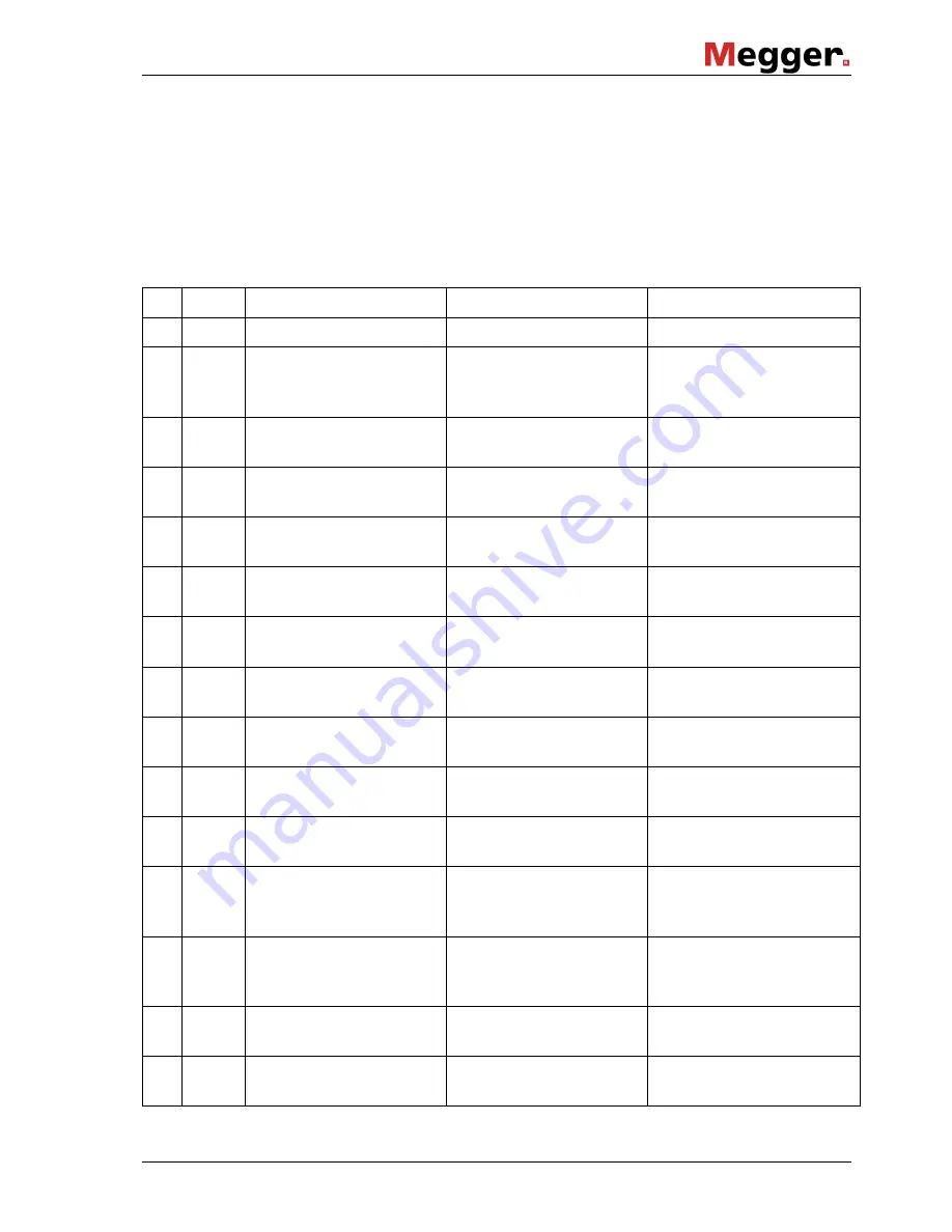
7.5.2  Operational Messages about State of System 

 
The following operational messages inform the operator about the current state of the 

system. 
You  don´t need to confirm  any of them. The system, however, expects the operator to 

make one of the entries listed in the table. 
 

Code 

Cl. 

Operational message  Description 

Input 

-  - 

[ Start-up screen] 

System is starting up. 

none 

-  U 

Connecting... 


System is connecting 

Master and Slave 

processors. 

none 

-  U 

Initiating system 


System is initializing 

parameters etc. 

none 

-  U 

Remove any card ! 


No card must be plug-

ged in during start-up.  

none 

      pull out  


      card ! 

-  U 

Ready.     OK:Start 


System is ready for 

starting a test. 

OK 

(or to   


Setup) 

-  U 

By card.   OK:Start 


System is ready for 

starting a test. 

OK 

(or to   


Setup 

-  U 

Stopped.  OK:Start 


System is ready for 

starting a test. 

OK 

(or to   


Setup) 

-  U 

Select mode   OK? 


System is waiting for 

input of mode.  

rotary knob + OK 

-  U 

Set voltage     OK? 


System is waiting for 

input of test voltage. 

rotary knob + OK 

-  U 

Set test time  OK? 


System is waiting for 

input of test time. 

rotary knob + OK 

-  U 

Set pulsing     OK? 


System is waiting for 

input of pulsing rate. 

rotary knob + OK 

-  U 

Insert SystemCard 


System is waiting for a 

system card to be 

inserted. 

none 

  insert 


  card ! 

-  U 

Without card only 


Operation mode can 

only be performed 

without system card 

none 

      pull out  


      card ! 

-  U 

Card is invalid ! 


System card not 

readable or invalid. 

none 

      pull out  


      card ! 

-  U 

Card is full ! 


System card is full.  

none 

      pull out  


      card ! 

Summary of Contents for TDS40

Page 1: ...Test and Diagnosis System TDS40 TDS60 Stand alone test operation Operating Manual Issue 01 01 2014 EN Item Nr 83549...

Page 2: ......

Page 3: ...CT17 9EN T 44 0 1304 502100 F 44 0 1 304 207342 E uksales megger com Dr Herbert Iann Str 6 D 96148 Baunach T 49 9544 68 0 F 49 9544 22 73 E sales sebakmt com Hagenuk KMT Kabelmesstechnik GmbH Megger...

Page 4: ...eby limited to a period of 12 months from the date of delivery Each component supplied by Megger within the context of warranty will also be covered by this warranty for the remaining period of time b...

Page 5: ...2 21 2 8 1 Operating Module 2 21 2 8 2 Display of the Operating Module 2 22 2 8 3 Connections 2 23 2 8 4 Protection Covers of the Module 2 24 2 8 5 Transportation Protection Bottom from the Operating...

Page 6: ...ating the Test and Diagnosis System with a SystemCard 6 50 6 5 Function User Setup User Level 6 52 6 6 Re Setting the System Settings Deleting the Print Templates 6 53 6 7 Adjustment of the System Tim...

Page 7: ...5 Selection of the pulse rate 4 35 Fig 16 Switching on high voltage 4 36 Fig 17 Display of the logged measurement values 4 36 Fig 18 Display of instantaneous data 4 37 Fig 19 Display of the set voltag...

Page 8: ...tes 6 54 Fig 41 Setup Date Time Saving by F1 6 54 Fig 42 Unscrewing the printer front cover 7 56 Fig 43 Removing the front cover 7 56 Fig 44 Removing the ribbon cartridge 7 56 Fig 45 Inserting the rib...

Page 9: ...riphery otherwise the safety of the system is jeopardised The user is obliged to immediately report any occurring change in the system to the supervisor in charge The operator is obliged to immediatel...

Page 10: ...may result in fatal or serious injury CAUTION Caution refer to accompanying manual for instructions Indicates a potential danger that may lead to slight or moderate injury The notes contain important...

Page 11: ...ting safety is only guaranteed if the delivered system is used as intended Incorrect use may result in danger to the operator to the system and the connected equipment The limits described under Techn...

Page 12: ...ations there is a danger that the operator of the fire extinguisher will get an electrical shock from a voltage arc over due to the powder dust created It is essential to observe the safety instructio...

Page 13: ...ble for the partial discharge diagnosis on medium voltage cables according to the standards In this stage of expansion the system is operated by remote control and can be operated in the VLF or DAC da...

Page 14: ...Testable cable capacitance in the VLF operation also see section 2 6 for full operating temperature range 2 2 F Basis 4 4 F Plus 0 8 F Basis 1 6 F Plus At normal temperatures 20 C and with restriction...

Page 15: ...ing on the model 55 kg 48 5 kg Basis 55 kg 55 5 kg Plus 85 kg 48 5 kg Basis 85 kg 55 5 kg Plus 2 4 Scope of Delivery and Options Equipment Power cord 2 5 m Earth cable 5 m HV connection cable 5 m HV c...

Page 16: ...annel PD partial discharge is small enough not to cause further erosion and so increase gas pressure The inversion of polarity on the one hand must be slow enough to exclude any transients caused by t...

Page 17: ...ed from the system resp discharged via a resistance Subsequently the polarity reversal is initiated The test voltage changes its polarity from minus to plus Depending on the size of capacitance of the...

Page 18: ...g with the negative DC source In contrast to this at the device option Plus the losses of a polarity reversal are immediately compensated The back up capacitor has the following tasks It slows the rin...

Page 19: ...2 19 2 6 Testable Cable Capacitance in VLF Mode...

Page 20: ...2 20 2 7 Cable Capacitance that Can be Diagnosed in DAC Mode TDS40 TDS60...

Page 21: ...Key Emergency Off 2 Analogue indication instrument test voltage kV 3 Display 4 Menu key F1 5 Menu key F2 6 Knob push button 7 Intake slot for the System Card 8 Protocol printer 9 Key HVOff red 10 Key...

Page 22: ...ng values 3 Representation of operator guidance status display Following signals are indicated in the line of operator guidance status display Fig 4 item 3 Operator guidance Select mode OK e g Status...

Page 23: ...inal clip for earth connection of the Operating module 3 Terminal clip for earth connection HV module 4 RJ45 network socket for the connection with the notebook required for remote control 5 Connector...

Page 24: ...2 24 2 8 4 Protection Covers of the Module VLF Test System Fig 6 Protection cover of the Operating module Fig 7 Shorting device Protection cover of the HV module...

Page 25: ...otection bottom from the Operating module Pull out in order to remove the transportation protection bottom Pull out in order to remove the transportation protection bottom Push in in order to fix the...

Page 26: ......

Page 27: ...nents or have them disconnected for the duration of your test at this site after having consulted the relevant supervisor and asked for his her permission Make sure this measure is carried out properl...

Page 28: ...nd diagnosis system is operated a second person must be present within viewing and hearing distance who can recognise possible hazards and press the Emergency Off key Never leave the test and diagnosi...

Page 29: ...nnector device side and end termination test object side of the movable high voltage connecting HV output socket of the HV module HV connector between HV module and operating module 3 2 Electrical Con...

Page 30: ...priate point and then to be attached to the Terminal clips of the operating module see Fig 5 item 2 and of the HV module see Fig 5 item 3 The HV connection cable with its HV connector has to be plugge...

Page 31: ...g 10 Connection of the external safety device As soon as the system has been connected to a mains outlet the red signal light lights up and signals that high voltage could be generated By using the Em...

Page 32: ......

Page 33: ...ushbutton Fig 3 item 12 the system can be operated using the knob push button Fig 3 item 6 and the display Fig 3 item 3 The following start menu is represented on the display Fig 3 item 3 after start...

Page 34: ...5 min up to 90 min test duration at maximum by turning the knob push button Fig 3 item 6 The adjusted test time has to be confirmed by pressure on the knob push button Fig 3 item 6 Use the information...

Page 35: ...maximum step voltage at the fault This peak is located with an earth fault locator e g ESG By turning the knob push button Fig 3 item 6 the SFL operation mode has to be selected Afterwards the voltage...

Page 36: ...em 9 lights up Under maintaining of the predetermined charging parameters the test voltage will be regulated to the adjusted test voltage level At the analogue indication instrument Fig 3 item 2 and o...

Page 37: ...18 Display of instantaneous data If the button F2 is pushed again the display changes back to the logged measured values Beyond this by clicking the menu button F1 the user can switch between the disp...

Page 38: ...test see section 6 4 after detection of an internal failure see section 7 5 In these cases the predefined discharging of the voltage source back up capacitor and test object follows too Attention The...

Page 39: ...3 item 5 and turning the knob push button Fig 3 item 6 the System info menu can be accessed When accessing this menu the software versions of several system components and the system ID you should hav...

Page 40: ...the space of its standard data Any re setting can be only carried out by the administrator The standard maximum voltage of the test system represents the default setting Adjustment of the rate of the...

Page 41: ...system is 2345 The first two digits of the password 23 have to be entered under 1 and the last two digits 45 have to be entered under 2 Any entered number sequence has to be confirmed by pressing the...

Page 42: ...ig 26 Setup Enter new password Fig 27 Setup New password stored 5 5 Returning to the Start Menu In order to return to the start menu you have to access either the Return or the Escape menu item If you...

Page 43: ...wn detection 6 2 Measurement of Leakage Current If a system is equipped with the optional Leakage Current measurement the leakage currents of the test object are indicated on the display during the te...

Page 44: ...out Standard After a cable test has been finished the protocol printout can be triggered from the start menu Fig 9 by pressing the F1 key once or repeatedly Depending on the print settings see above t...

Page 45: ...settings of the SystemCard whether these print templates are permanently stored in the test system configuration or are only valid for the period of the cable test under way In order to test the layou...

Page 46: ...rint settings back to your normal protocol printout mode after you performed a test printout Note a SystemCard is used with the system see section 6 4 make sure that when parametrizing the SystemCard...

Page 47: ...or the cable test under way A SystemCard can be prepared for parametrizing the system Parameter card In this case the SystemCard changes the settings of the system as specified under WinkisVLF before...

Page 48: ...been planned Furthermore this will allow you to prepare volatile print templates individual header lines and footer lines for the ongoing cable test or non volatile print templates as default protocol...

Page 49: ...e card to a PC where it can be analyzed and archived using the WinkisVLF software For detailed information about the WinkisVLF software please refer to its online help By pressing the F2 key Fig 3 ite...

Page 50: ...rged status message appears Otherwise data may be lost 6 4 4 Operating the Test and Diagnosis System with a SystemCard In order to use a SystemCard for parametrizing the test and diagnosis system or s...

Page 51: ...4 1 Attention If the SystemCard is removed during an ongoing cable test the test is interrupted For the special case of a SystemCard intended to change the settings of the test system permanently see...

Page 52: ...on 6 4 3 or parametrizing the system using a SystemCard see section 6 4 2 Fig 36 Setup User profile By setting the user level to Single the system can only be operated with a parametrized SystemCard T...

Page 53: ...he functions of this menu can be activated by pressing the F1 key or F2 key respectively By pressing the knob push button the menu can be left without triggering a function Fig 37 Setup Memory F1 Relo...

Page 54: ...n be adjusted By turning the knob push button the value of the selected segment is changed You can toggle through the segments by pressing the knob push button After all segments have been set the dat...

Page 55: ...er also offers its customers on site service Please contact your service centre as needed 7 1 Replacing Fuses If the device cannot be switched on even though it is connected to the mains power supply...

Page 56: ...der to exchange the ribbon press down the left edge of the ink ribbon cartridge marked Push and Eject Fig 44 The cartridge will come off on the right hand side and can now be removed Tighten the ribbo...

Page 57: ...2 inches of paper stand out of the printer unit Insert the new paper roll with the spindle into the paper container und tension the paper After that again insert the ribbon cartridge into the printer...

Page 58: ...5 1 Classification of Messages Operational and error messages occurring during the operation of the test and diagnosis system are classified as follows Symbol Class Response What to do U Operational...

Page 59: ...em is ready for starting a test OK or to Setup U By card OK Start System is ready for starting a test OK or to Setup U Stopped OK Start System is ready for starting a test OK or to Setup U Select mode...

Page 60: ...preparing high voltage HVOff or OK U Holding HVOff System is preparing high voltage HVOff or OK U Discharging System is discharging and earthing after HVOff none U F1 retry F2 reboot System is waitin...

Page 61: ...up Prompting to make entry rotary knob OK U F1 F2 else OK In Setup query of Memory F1 or F2 or OK abortion U F1 F2 else OK In Setup query of Calibration F1 or F2 or OK abortion U Set service mode In S...

Page 62: ...safety loop External safety loop is open Close emergency loop C Door contact s At least one door contact is open Close doors of vehicle C Module coupling Connection between modules is interrupted Conn...

Page 63: ...ult of a cable test C Test time over High voltage has been switched off by system after test time has elapsed No action required C HVOff by OWTS M HV is switched off via the connected OWTS system No a...

Page 64: ...pt from the slave via LON LON Bus wiring power supply 03 F Slave not ready The master has not received any confirmation from the slave on its request LON Bus wiring power supply 04 F Unknown slave The...

Page 65: ...rol is interrupted Hardware damage EMC trouble in module check cable between LON and module 14 T Parameter error The slave does not per form any parameter setting because the set of parameters is faul...

Page 66: ...e switches and hardware signal XXXn on module 24 N Dischg switch The discharge switch has not opened Check control of discharge switch and hardware signal XXXn on module 25 N HV source on Return messa...

Page 67: ...d card format There is a formatting error on the system card Card Device Command Header erroneous print text line too long Data Page not empty 36 N No card access Some error has occurred when reading...

Page 68: ...or customer service 46 W DEMO MODE ON The system has been set to demo mode via the setup menu Should not appear during regular operation Demo mode is only for service purposes 47 W C values stored Cal...

Page 69: ...if necessary 57 F Illegal config Configuration data of master and slave differ Software problem Must not appear during regular operation 58 N NOT GROUNDED Danger The system cannot ensure proper dis c...

Page 70: ...teps 69 R Task conflict Software problem must not occur during operating 70 R Not connected 71 R Watchdog failed 72 R Card inserted In the remote control mode a SystemCard has been inserted Remove the...

Page 71: ...ie z me nor da ka iztr d jumu uz kura t atrodas nedr kst izmest kop ar parastiem m jsaimniec bas atkritumiem T k tas ir izstr d jums ko cits citam p rdod un lieto tikai uz mumi tad to nedr kst ar izme...

Reviews: