41
PN: 81127
Rev 4, 6/2017
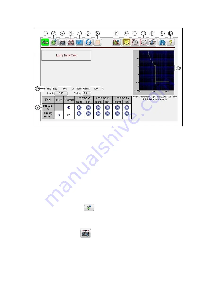
Figure 32 - Advanced Pickup and Timing Test Screen
3.5.2
Advanced Pickup and Timing Test Screen
Selection of a specific manufacturer’s circuit breaker will result in a test screen looking something similar
to the above test screen. Obviously curve wave shapes will vary depending on the breaker selected, and
whether or not it includes Long Time, Short Time and Instantaneous curves. A description of the breaker
selected and/or the curve will appear below the Time-Current curves displayed as in the example above.
Different icons and input setting windows will appear or disappear depending on the breaker selected.
The following descriptions are provided for each possible icon and setting window shown in the above
figure.
.
3.5.2.1
PC or STVI to SPI connection button
Click on the button and the PC or the STVI will auto detect the SPI unit connected and automatically set
the IP address through the Ethernet ports. If the button shows two red Xs it indicates that there is no
communication to the SPI. If the background
color is green it indicates that the unit is ‘on-line’ and ready
for operation.
3.5.2.2
Configuration button
Press the button to go to the STVI Configuration Screen. See Section 2.3.1 Configuration for more
information of the Configuration Screen.
3.5.2.3
View Report button
This button will add the present test result to the report. It also displays the report and allows the user to,
enter limits, comments or deficiencies. Reports can be saved to the STVI internal memory and


