background image

Page 22

Operation

optoNCDT ILR 1181 / 1182

6.2 

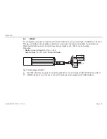
RS422

For configuration purposes and permanent data transmissions over a greater length, the RS422 can be used. 
This type of interface is insusceptible to interference and noise influences and qualifies for industrial use. 
Where twisted cable pairs are involved, transmissions lengths up to 1200 m can be handled.
Properties:

 - Maximum input voltage RX+, RX- = ±14 V
 - Output voltage TX ±2 V, 2 x 50 W load differential 

U

V

GND

<<RX+

<<RX -

TX ->>

TX+>>

wh te

brown

red

red/blue

gray

pink

Fig. 12 Wiring diagram RS422

i

  The RS422 interface is popular in industrial applications. Use an adequate USB TO RS422 converter or 

a RS422 interface card in the case of your PC/ notebook is just equipped with USB interfaces.

Summary of Contents for ILR 1181-30

Page 1: ...ILR 1181 30 ILR 1182 30 Instruction Manual optoNCDT ILR 1181 1182...

Page 2: ...PSILON MESSTECHNIK GmbH Co KG K nigbacher Strasse 15 94496 Ortenburg Germany Tel 49 0 8542 168 0 Fax 49 0 8542 168 90 e mail info micro epsilon de www micro epsilon com Certified acc to DIN EN ISO 900...

Page 3: ...ass 9 3 Functional Principle Technical Data 11 4 Delivery 14 4 1 Supplied Items Unpacking 14 4 2 Storage 14 5 Installation 15 5 1 Sensor Mounting 15 5 2 Reflector Mounting 16 5 3 Electrical Connection...

Page 4: ...lay Set Scale Factor 34 7 3 6 SEx Display Set Error Mode 35 7 3 7 ACx x Display Set ALARM Center 35 7 3 8 AH Display Set ALARM Hysterese 35 7 3 9 AWx x Display Set ALARM Width 36 7 3 10 RBx x Display...

Page 5: ...Page 5 optoNCDT ILR 1181 1182 12 Warranty 49 13 Service Repair 49 14 Decommissioning Disposal 50 Appendix A 1 Accessories 51 A 2 Factory Setting 53...

Page 6: ...Page 6 optoNCDT ILR 1181 1182...

Page 7: ...se specified herein may result in hazardous radiation exposure Avoid unnecessary laser radiation to be exposed to the human body Switch off the sensor for cleaning and maintenance Switch off the senso...

Page 8: ...ilure of the measuring device i Information and warning signs must not be removed 1 3 Notes on CE Identification The following applies to the ILR 1181 1182 EU directive 2014 30 EU EU directive 2011 65...

Page 9: ...y 65 no condensation Ambient pressure atmospheric pressure 2 Laser Class The optoNCDT ILR 1181 30 1182 30 sensors operates with a wavelength of 650 nm visible red The maximum optical output is 1 mW Th...

Page 10: ...fully observed at all times The sensor complies with all applicable laws for the manufac turer of laser devices Although the laser output is low looking directly into the laser beam must be avoided D...

Page 11: ...pply voltage By external triggering in remote trigger mode Using the autostart trigger function For a more detailed description of these four trigger options see Chap 7 Special performance features ar...

Page 12: ...sensor Technical data Model ILR 1181 30 ILR 1182 30 Measuring range 1 0 1 50 m on natural diffuse reflective surfaces 50 m up to max 150 m on reflection board Linearity 2 2 mm 15 C 30 C 5 mm 10 C 47...

Page 13: ...r distance tracking continuous measurement Analog output 4 mA 20 mA 16 bit DAC Load 500 Ohm temperature drift max 50 ppm K Switching output Open Collector HIGH UV 2 V LOW 2 V rated for loads up to 0 5...

Page 14: ...n manual Check the delivery for completeness and shipping damage immediately after unpacking In case of damage or missing parts please contact the manufacturer or supplier immediately You will find op...

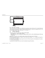
Page 15: ...the installation slots The laser beam must be directed perpendicularly onto the surface of the target In case of misalign ment it is possible that the measurement results will not always be accurate...

Page 16: ...to moving and static targets in the range of 0 1 50 m on diffuse surfaces between 50 m and 150 m on reflectors for example reflector film from 3M Scotchlite Engineer Grade type I series 3290 It is pos...

Page 17: ...ing to comply with IP 65 require ments This connector type guarantees optimized screening and a high IP degree The required counterpart is an adequate female cable connector with grading ring availabl...

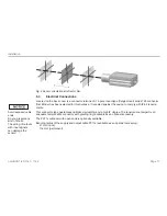
Page 18: ...ing values of voltages load rates and logic levels are in accordance with RS232 and RS422 standard requirements All outputs are protected against steady short circuit currents A power supply and outpu...

Page 19: ...t screening three essential rules must be followed 1 For integration with vehicles Where the attachment point and the reference potential GND or have equal potentials it may be necessary to electrical...

Page 20: ...he sensor as part of preparative actions in the designated working site oriented onto the target and keep it in a stable position The target to be measured should preferentially have a homogeneous whi...

Page 21: ...guration Parameter Baud rate 9 6 kBaud 2 4 4 8 19 2 38 4 Start Stop bit 1 Data bits 8 Handshake none Parity none Protocol ASCII Properties Maximum input voltage RxD 25 V Output voltage TxD 5 V UV GND...

Page 22: ...use Where twisted cable pairs are involved transmissions lengths up to 1200 m can be handled Properties Maximum input voltage RX RX 14 V Output voltage TX 2 V 2 x 50 W load differential UV GND RX RX T...

Page 23: ...e three parameters Alarm Center AC Alarm Hystere sis AH and Alarm Width see Chap 7 3 7 et seq The range which will be subject to monitoring begins at AC and ends at AC AW Switching transitions can be...

Page 24: ...nsecutively you find the parameters AC AW and AH in dependence on SF AC2 AH0 2 AW3 SF1 AC2000 AH200 AW3000 SF1000 Distance m increases 1 8 1 9 2 0 2 1 2 2 5 0 5 1 5 2 AH L L L H H H H L L AH H H H L L...

Page 25: ...log output The purpose of the analog output is to allow transmission of analog measured values via a 4 20 mA inter face The amount of current which is injected into the line of transmission is proport...

Page 26: ...20 SE 2 SE 1 RB RE 0 Dist Iout mA Fig 16 Output current diagram for RE RB and RE RB Examples The distance of a moving target is to be measured in a range of 2 m up to 6 m At a distance of 2 m the sen...

Page 27: ...ed blue max 24 V UV green Fig 17 Wiring diagram of trigger input The trigger input is intended for triggering a distance measurement with an external signal that is applied as a voltage pulse between...

Page 28: ...lues by running an initialization routine Command Description ID Online help to the control commands DT Starts distance tracking DS Starts distance tracking 7 m DW Starts distance tracking on white ta...

Page 29: ...e used for com mands Any command which is to be sent to the sensor must be terminated by a hexadecimal 0Dh carriage return character Where decimal digits are to be entered they must be separated by pe...

Page 30: ...asuring time The minimum time to measure is 160 ms the maximum time is 6 s If the measuring signal fails to reach a specified quality within six seconds an error message is output The time to measure...

Page 31: ...uring rate of 50 Hz Stable measuring values only with a white target board at the target Homogeneous motions with maximum 4 m s High rate of measurement included preceding measuring values in the proc...

Page 32: ...ternal Temperature TP queries the value of the inner sensor temperature in C i In tracking mode the inner temperature may exceed the surrounding temperature level by as much as 10 K 7 3 2 SAx Display...

Page 33: ...Distance 4 996 m SF10 dec 49 960 hex 00C328 49960 4996 mm SF10 7 3 4 STx Display Set Measuring Time Standard setting 0 Measuring time is directly conditional on the selected measuring mode As a genera...

Page 34: ...a measuring time setting of ST 2 E15 will be output following measurement The user must increase the measuring time in this case i One should work in DW or DX mode where stable measuring times are re...

Page 35: ...g output and analog output 7 3 7 ACx x Display Set ALARM Center Standard setting 0 1 AC sets the beginning of the distance range for which the switching output will be turned active The length of this...

Page 36: ...ll correspond to the current that was set via parameter SE see Chap 7 3 6 7 3 11 REx x Display Set Distance of Lout 20mA Standard setting 30 RE Range End corresponds to the end point of the distance r...

Page 37: ...measuring value will be corrected accordingly Z Stands for the number of values that are out of the permissible value range in the event of out of toler ance values arriving in succession the most rec...

Page 38: ...falling type HIGH to LOW transition 7 3 14 TMx y Display Set Trigger Mode Trigger Level Standard setting 0 1 TM provides parameter the setting option for the auto start trigger function which allows e...

Page 39: ...ctive that means one measurement is triggered HIGH LOW DM on DM off t 7 3 15 BRx Display Set Baud Rate Standard setting 9600 Available baud rate BR settings are 2400 4800 9600 19200 38400 Faulty entri...

Page 40: ...in with distance tracking on turning on power Possible versions DT DS DW DX DF DM TP LO ID 7 3 17 OFx x Display Set Distance Offset Standard setting 0 With the help of OF offset define a zero point fo...

Page 41: ...ay format SD d measure time ST 0 scale factor SF 1 error mode SE 1 ALARM center AC 20 ALARM hysterese AH 0 1 ALARM width AW 10 distance of Iout 4mA RB 15 distance of Iout 20mA RE 25 remove measurement...

Page 42: ...e SA 1 display format SD d measure time ST 0 scale factor SF 1 error mode SE 1 ALARM center AC 0 1 ALARM hysterese AH 0 001 ALARM width AW 100 distance of Iout 4mA RB 0 1 distance of Iout 20mA RE 30 r...

Page 43: ...face are popular in industrial applications Use an adequate USB TO RS232 converter in the case of your PC notebook is just equipped with USB interfaces Preparation Measuring Connect your controller to...

Page 44: ...9 600 Baud Data format 8 Data bits Parity None Start Stopbit 1 Flow control No Click on the OK button Type the command ID and press the button EN TER The sensor reads out the commands for the distanc...

Page 45: ...mmand will only be displayed if Local echo is enabled This function can be ac cessed via file menu File Properties Settings ASCII Setup Save finally unless performed earlier the current hyperterminal...

Page 46: ...Enter SAx Enter display set average value 1 20 SD Enter SDd Enter display set display format d h ST Enter STx Enter display set measure time 0 25 SF Enter SFx x Enter display set scale factor SE Enter...

Page 47: ...ects remove or cover E18 Only in DX mode 50 Hz too much differ ence between measured and pre calculated value Check path from distance meter to target being measured for obstacles E19 Only in DX mode...

Page 48: ...ue in interface communication Parity error SIO Check external software parity setting E63 SIO overflow Check time of emitted signals in application soft ware integrate delay on transmission if necessa...

Page 49: ...contract apply in full MICRO EPSILON will specifically not be responsible for eventual consequential damages MICRO EPSILON always strives to supply the customers with the finest and most advanced equ...

Page 50: ...power supply and output cable on the sensor Incorrect disposal may cause harm to the environment Dispose of the device its components and accessories as well as the packaging materials in compli ance...

Page 51: ...CDT ILR 1181 1182 Appendix A 1 Accessories PC11xx Power supply output cable 2 m up to 30 m length subject to order PC1100 3 RS232 Power supply output cable RS232 3 m length FC1100 Female cable connect...

Page 52: ...sal optoNCDT ILR 1181 1182 ILR PG118x Protective glass Protective glass for ILR118x ILR MP118x Mounting plate for ILR118x Mounting plate for ILR118x ILR MT118x Mounting brackets Mounting brackets with...

Page 53: ...ry Setting Parameter Setting SA 1 SD d ST 0 SF 1 SE 1 AC 0 1 AH 0 001 AW 100 RB 0 1 i At the parameters AC AH TD TM RM the values are to separate by space Decimal tag is a dot 2Ehex The command PR res...

Page 54: ...N MESSTECHNIK GmbH Co KG K nigbacher Str 15 94496 Ortenburg Germany Tel 49 0 8542 168 0 Fax 49 0 8542 168 90 info micro epsilon de www micro epsilon com X9751184 A051116HDR X9751184 A05 MICRO EPSILON...

Reviews: