Page 23
Operation
optoNCDT ILR 1181 / 1182
6.3
Digital Switching Output
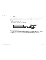
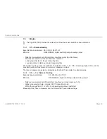
Properties: Open collector
- HIGH = U
V
– 2 V
- LOW < 2 V
- rated for loads up to 0.5 A
- with switching threshold, latitude (width) and hysteresis selectable
U
V
GND
I
L
= 10 ... 500 mA
red
red/blue
black
Fig. 13 Wiring diagram of digital switching output
For example, using the digital switching output, an object which was selected for measurement can be
monitored for excession of a threshold value. To do this, parameter settings for a measurement window are
required. Settings for this window can be made via the three parameters: Alarm Center (AC), Alarm Hystere-
sis (AH) and Alarm Width, see Chap.
7.3.7
et seq..
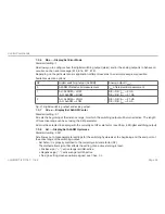
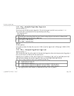
The range which will be subject to monitoring begins at AC and ends at AC+AW. Switching transitions can be
set via parameter AH. The logic state of the switching output follows from the mathematical sign of AH. In the
case of a positive AH, the output switches
- with increasing distance:
from LOW to HIGH if the distance is found to be greater than (AC + AH/2).
from HIGH to LOW if the distance is found to be greater than (AC + AW + AH/2)
- with decreasing distance:
from LOW to HIGH if the distance is found to be smaller than (AC + AW - AH/2).
from LOW to HIGH the distance is found to be smaller than (AC - AH/2).
In the case of a negative AH, the output switching pattern will be inverse.


