Expansion Tank
In the mini-chiller unit, the expansion tank is located on the storage tank. However, this tank is
only available in the larger units, i.e. AC 75B, AC 100B, AC 125B.
For the smaller units, i.e. AC 40A, AC 50A and AC 58A, the expansion tank must be located
externally.
Generally, the expansion tank provides a space into which the water can expand or from which it
can contract as the water undergoes volumetric changes with respect to changes in temperature.
Therefore, it is
recommended
for such an expansion tank to be installed externally for the
smaller mini-chillers when running cooling only cycle, but it is
compulsory
to do so for the heat
pump units with both cooling and heating cycles. Failure to do so will cause serious damage to
the hydraulic components in the unit and also may cause cracking of the piping network. This is
due to the expansion of the hot water in the pipes.
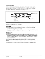
To allow for this expansion or contraction, the tank provides an interface point between the water
and a compressible gas (e.g. air or nitrogen). There are 3 types of expansion tank available:
a. A closed tank which contains a captured volume of air and water
b. An open tank, i.e. with the water surface open to the atmosphere
c. A diaphragm tank, in which a flexible membrane is inserted between the air the water
The expansion tank which is used in the mini chiller units is of type (c). This type is
recommended as the diaphragm will prevent the air dissolving into the water.
Tank body
Air
Diaphragm
Water
Connecting
pipe
The tank is usually installed vertically, either upwards or downwards. However, due to space
considerations, it is also possible to install it horizontally.
Downward installation
Horizontal
installation
Section 6
Page 90
Summary of Contents for AC 40A
Page 1: ...AM MAC ...
Page 153: ...Appendix 1 ...
Page 154: ...Appendix 2 Appendix 2 ...
Page 157: ...GRAPH OF PRESSURE DROP VS FLOW FOR VARIOUS C V RATINGS Appendix 5 1 ...
Page 158: ......
Page 159: ...Water Capacity Graph Appendix 5 2 ...
Page 160: ...CHART 3 FRICTION LOSS FOR CLOSED PIPING SYSTEMS Appendix 6 1 ...
Page 161: ...CHART 4 FRICTION LOSS FOR OPEN PIPING SYSTEMS Appendix 6 2 ...
Page 162: ...CHART 5 FRICTION LOSS FOR CLOSED AND OPEN PIPING SYSTEMS Appendix 6 3 ...
Page 168: ...Appendix 8 Appendix 8 ...
Page 169: ...Appendix 8 1 ...
Page 170: ...Appendix 8 2 ...
Page 171: ...Appendix 8 3 ...
Page 172: ...Appendix 8 4 ...
Page 173: ...Appendix 8 5 Appendix 8 5 ...
Page 174: ...Appendix 8 6 Appendix 8 6 ...
Page 175: ...Appendix 8 7 Appendix 8 7 ...
Page 176: ...Appendix 9 ...
Page 178: ...Appendix 11 1 Appendix 11 1 ...
Page 179: ...Appendix 11 2 Appendix 11 2 ...
Page 180: ...Appendix 13 ...
Page 181: ...Appendix 13 1 ...
Page 182: ...Appendix 14 Appendix 14 ...
Page 183: ...Appendix 15 1 Appendix 15 1 ...
Page 186: ...Appendix 17 Appendix 17 ...
Page 187: ...Appendix 18 ...
Page 188: ...CE20DW CE25DW Note PRESSURE DROP CORRECTION FACTOR 1 2947 0 0021 EWTºF Appendix 19 ...
Page 189: ... 2003 McQuay International 603 55194922 www mcquayup com ISO 9002 REGISTERED ...


