background image

EXIT PWR

ALARM

POWER /

SOLAR IN

BATTERY

INPUT

OPENING

CLOSING

CLOSING

OPENING

ERD

OBD PORT

BLACK BOX

PROGRAMMING

SOLAR MODE

PROGRAM

MOTOR

OVER

LOAD

ERD

MOTOR

OVER

LOAD

MAX

OFF

MAX

SENSE

MAX

SENSE

BATTERY

BACKUP MODE

ERD SENSITIVITY

MOTION CONTROL

OPEN

GATE SPEED

MAG

LOCK

UL

ENTRAP

PRIMARY/

SECONDARY

LINK

STOP

CLOSE

MOTOR

INPUTS

CLOSE

TIMER

MAGLOCK

DELAY

JOG

BATTERY

TEST

INPUT

ERROR

BATTERY

BATTERY

IN USE

REPLACE

BATTERY

LEAVE

CLOSED

LEAVE

OPEN

OPEN

1 TIME

BATTERY VOLTAGE

E

F

1/2

RESET /

MANUAL

RELEASE

ID

PLUG

LINK

OK

MODULE

PORT

MOTOR

POSITION

INPUTS

SLIDER

LIMIT

SWING

LIMIT

GND

OPEN ONLY 

NC

OPEN ONLY 

10K

PHOTO CLS 

NC

OPEN/CLS 

NC

GND

12VDC OUT

GND

GND

GND

GND

GND

GND

JOG RIGHT

JOG LEFT

TAMPER IN

TAMPER NO

GATE DISABLE

MANUAL RELEASE

KEYPAD / CARD

GND

(-)

(+)

GND

GND

MAX OPEN

FIRE DEPT

RADIO GND

RADIO SIGNAL

STRIKE

CLOSE

COM

COM

STOP

OPEN

CLS ONLY 

10K

OPEN/CLS 

10K

12VDC OUT

NO

COM

NC

ID PLUG

ERROR

24VDC OUTPUT

12VDC OUTPUT

GND

GND

GND

LOOP PWR

OFF

PRIMARY

LEFT

ON/OFF

BATTERY

RIGHT

SECONDARY

ON

QUICK

CLOSE

OPEN

LEFT

OPEN

   RIGHT

GATE

OFF

1

2

3

4

5

6

7

8

9

10

1

2

3

4

5

6

MIN

MIN

MAX

MAX

ON

OFF

2.5 sec

1.5 sec

FAULTS

OPERATOR

MATRIX III

OFF

OFF

3

1

14

16

MIN

16

MIN

12

9

7

3

1

14

12

9

7

UL SENSOR N.C.

UL SENSOR 10K

POWER

MODE A

MODE B

EXIT

LOOP

LOOP

LOOP

CENTER

SAFETY

GATE OPEN

COM

GATE CLOSED

MIN

MATRIX III
SWING / SLIDE

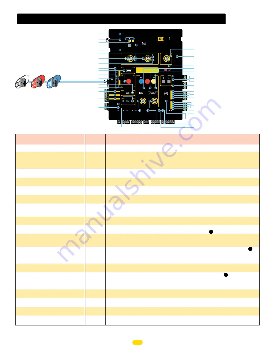
matrix III led troubleshooting

Table continued on next page

12.

 ID PLUG ERROR

15.

 EXIT LOOP

14.

 PRIMARY/SECONDARY

13.

 SOLAR MODE

5.

 POWER

6.

 ERD

7.

 MAX SENSE

8.

 MOTOR OVERLOAD

9.

 MANUAL RELEASE/RESET

20.

 CLOSE TIMER

21.

 SLIDER LIMIT

22.

 ON/OFF BATTERY

23.

 QUICK CLOSE

24.

 OPEN LEFT

25.

 OPEN RIGHT

26.

 GATE OPEN

27.

 GATE CLOSED

29.

 OPEN ONLY NC

30.

 PHOTO CLOSE NC

31.

 OPEN / CLOSE NC

32.

 12VDC OUT

28.

 MAGLOCK

10.

 OBD PORT

11.

 PROGRAM

4.

 REPLACE BATTERY

3.

 BATTERY VOLTAGE

2.

 BATTERY IN USE

1.

 BATTERY INPUT ERROR

16.

 CENTER LOOP

17.

 SAFETY LOOP

18.

 12 VDC

19.

 24 VDC

33.

 OPEN ONLY 10K

34.

 CLOSE ONLY 10K

35.

 OPEN / CLOSE 10K

36.

 12VDC OUT

37.

 UL ENTRAPMENT

42.

 GATE SPEED

40.

 LINK OK

41.

 MANUAL RELEASE

38.

 GATE TAMPER

39.

 GATE DISABLE

ID plug 

MUST

 be plugged in.

MAX

1500 PRO

MAX

2200 PRO

MAX

F18 PRO

MAX

 1500

MAX 2200

MAX F18

Matrix III LED

Problem Condition

Solution(s) for

Problem Condition

Normal

LED

“BATTERY IN ERROR” LED is ON.
“BATTERY IN USE” LED is ON

“BATTERY VOLTAGE (E 1/2 F)” LEDs, only “E” 
is ON.
“REPLACE BATTERY” LED is ON.

“BATTERY IN USE” and “POWER” LED  are 
FLASHING
PRIMARY Matrix III “LINK OK” LED is OFF

SECONDARY Matrix III “LINK OK” LED is OFF

“UL Entrap” LED is ON

“ERD” LED is FLASHING

“PHOTO CLS” LED is ON
“CLS ONLY 10K” LED is ON

“PHOTO CLS” LED is flashing
“CLS ONLY 10K” LED is flashing

“OPEN ONLY” LED is ON

“OPEN ONLY” LED is FLASHING

“MAX SENSE” LED is ON

“MANUAL RELEASE/RESET” LED is ON but 
manual release is not working
“OBD PORT” LED is FLASHING

“PROGRAM” LED is FLASHING

 “BATTERY Plug” not plugged in to “BATTERY IN” port.

 AC power is lost, operator is in battery back-up mode.

 Check if Toroid box AC POWER ON/OFF SWITCH is ON.


Measure power input DC voltage on Matrix 1 (“24V/GND” - 2-pin black connector), (expected reading 
34 VDC if AC on, 25VDC if on battery back-up).

 Battery is very LOW. Check if AC power ON/OFF switch is ON. If so, check AC power.

 Battery needs to be replaced if BATTERY TEST fails and “REPLACE BATTERY” LED is ON.

 Battery not plugged in to BATTERY INPUT port.

 Check if limit sensors are plugged into PRIMARY MATRIX III “SLIDER LIMIT” input.

 Check wiring between PRIMARY RS485 (+,-, gnd) and SECONDARY RS485 (+,-, gnd) terminals, 

connect [(+) to (+)], [(-) to (-)] and [GND to GND].

 Check if limit sensors are plugged into SECONDARY Matrix III “SLIDER LIMIT” input.

 An entrapment event has occurred, check if an entrapment sensor was triggered (see if PHOTO CLS,

OPEN ONLY, or OPEN/CLS LEDs are on).

 An ERD event may have occurred. Check for gate obstruction.

 ERD sensitivity is too high for application. Re-adjust ERD setting, (see     ).

 Sensor on PHOTO CLS or CLS ONLY 10K inputs (photocell or edge) may have detected an obstruction 

while closing gate.

 Photocell on PHOTO CLS or CLS ONLY 10K inputs is misaligned with reflector.

 Sensor on PHOTO CLS or CLS ONLY 10k inputs (photocell or edge) may not be wired properly, (see     ).

 Sensor is NOT a N.C. monitored sensor that is UL325 2018 compliant.

 Sensor might need to be re-learned.

 Sensor is damaged or malfunctioning.

 Sensor on OPEN ONLY input (photocell or edge) may have detected an obstruction while cycling gate.

 Photocell on OPEN ONLY input is misaligned with reflector.

 Sensor on OPEN ONLY input (photocell or edge) may not be wired properly, (see     ).

 Sensor is NOT a N.C. monitored sensor that is UL325 2018 compliant.

 Sensor on OPEN ONLY is damaged or malfunctioning.

 Sensor might need to be re-learned.

 MOST sensitive setting for ERD entrapment detection. Select a less sensitive setting (recommend level 

10 thru 16)

 Connected external device to MANUAL RELEASE input is not working, check wiring. replace device.

 Up to 8000 event history and error codes are being downloaded to connected flash drive. Up to 5 min.

 Program button has been pressed and programming mode is active. Press button again to leave 

programming mode.

1

OFF

2

OFF

3

OFF

4

OFF / ON

2 / 5

ON

40

ON

40

ON

37

ON

6

OFF

30 / 34

OFF

30 / 34

OFF

29 / 33

OFF

29 / 33

OFF

7

OFF

9 / 41

OFF

10

OFF

11

8

5

5

21

UL 325 2018 Standard - MAX 1500 PRO/2200 PRO/F18 PRO Matrix III Install 

Version 7a

Summary of Contents for 1500 PRO

Page 1: ...om 4009963 Residential Commercial Brushless DC Slide Gate Operators Made in USA CONFORMS TO UL STD 325 MAX 1500 PRO 2200 PRO UL CLASS I II III IV MAX F18 PRO UL CLASS III IV ONLY CERTIFIED TO CAN CSA...

Page 2: ...t lors de l ouverture et de la fermeture la barri re doit tre install e dans un endroit o la barri re et les structures avoisinantes sont suffisamment loign es l une de l autre Les barriers battantes...

Page 3: ...1 Au moins un capteur de contact doit tre situ o il existe un risque de coincement ou d obstruction comme sur le bord d ouverture sur le bord de fermeture et sur les poteaux mont s sur l int rieur ou...

Page 4: ...etest the gate operator properly can increase the risk of injury or death 4 V rifiez le fonctionnement de l ouvre barri re une fois par mois Le sens de la course DOIT s inverser lorsque la barri re en...

Page 5: ...25 model classifications A Inherent entrapment protection system B1 Provision for connection of a non contact sensor photoelectric sensor or the equivalent B2 Provision for connection of a contact sen...

Page 6: ...stalled where entrapment or pinch point exist A minimum of TWO entrapment protection sensors MUST be installed ONE in EACH direction of gate travel or operator will NOT function Physical Stops Install...

Page 7: ...29 UL 325 Class of Operation MAX 1500 PRO 2200 PRO Class I II III IV MAX F18 PRO Class III IV ONLY Gate Type Vehicular Slide Gate Max Gate Length 50 ft Max Gate Weight MAX 1500 PRO 1500 lbs Level Gate...

Page 8: ...round to avoid flooding Concrete Depth Note The heavier the gate the deeper the concrete pad should be At least two feet recommended for heavier gate Secure gate operator to concrete pad with four 4 1...

Page 9: ...or is NOT parallel to gate Chain is NOT parallel to gate DO NOT mount chain bracket too high on gate NO NO YES YES YES YES Drive Gear NOTE The chain should sag no more than one 1 inch per 10 feet of t...

Page 10: ...75 7 5 7 5 6 75 Cover 1 5 4 5 6 5 8 625 12 75 Conduit Area Outside Property Inside Property Input Power Physical Stop Conduit Run Operator MUST be level Concrete Pad Check local building codes in your...

Page 11: ...heel Approx 1 5 Pulley Wheel Safety Cover Gate YES YES Modify Cover for Rear Mounting Position 16 5 Cut out cover between new hole and existing chain exit slot Make sure cuts are plumb with existing c...

Page 12: ...Amp Select Input Voltage 115VAC or 230VAC 1 1 5 V MAX Toroid Box ac input power 2 GFCI Outlet NOT provided DANGER HIGH VOLTAGE Additional Gang Box Choose either 115V or 230V setting on input AC power...

Page 13: ...r or F Bat ter y Mo dul e Ground within 3 ft of operator Any of the THREE Chassis Grounds can be used They are located next to the gear reducer DO NOT remove any existing green ground wires 1 2 3 Grou...

Page 14: ...C UL SENSOR 10K entrapment protection wiring 5 Entrapment Protection Device Options and Locations Beam 5 or LESS from CLOSED gate Conduit Entrapment Area CLOSING Direction Photocell Wall Gate Closed...

Page 15: ...Mini Edge Contact Edge Sensor ASO Edge Thin Edge MAX Edge 1 Contact Edge Sensor Test Connected Sensors Test ALL connected entrapment protection sensors using learn mode 1 Press and HOLD the STOP butt...

Page 16: ...PEN GATE SPEED MAG LOCK UL ENTRAP PRIMARY SECONDARY LINK STOP CLOSE MOTOR INPUTS CLOSE TIMER MAGLOCK DELAY JOG BATTERY TEST INPUT ERROR BATTERY BATTERY IN USE REPLACE BATTERY LEAVE CLOSED LEAVE OPEN O...

Page 17: ...ter clockwise to reduce gate sensitivity while testing ERD until desired results is attained LED remains OFF for all but position 1 IMPORTANT When satisfied with ERD adjustment cycle the gate 3 or 4 t...

Page 18: ...Detectors to HIGH sensitivity to avoid false trigger NOTE DO NOT select the PULSED output option for Loop Detectors EDI Loop Detector EDI Loop Detector Low Current Draw ON 1 2 3 4 5 6 7 8 5 Op tim um...

Page 19: ...en wired to indicated inputs MUST be LEARNED BEFORE they will be MONITORED 2 Press and HOLD the STOP button then the OPEN button together until beeping is heard learn mode begins DO NOT press the OPEN...

Page 20: ...EN OPEN 1 TIME BATTERY VOLTAGE E F 1 2 RESET MANUAL RELEASE ID PLUG LINK OK MODULE PORT MOTOR POSITION INPUTS SLIDER LIMIT SWING LIMIT OPEN ONLY NC OPEN ONLY 10K PHOTO CLS NC OPEN CLS NC GND 12VDC OUT...

Page 21: ...servicing the operator to prevent the switch from accidentally being turned ON during normal operation Plug the wire back in and turn ON the switch only while servicing the operator This can prevent...

Page 22: ...3 4 5 6 7 8 9 10 1 2 3 4 5 6 MIN MIN MAX MAX ON OFF 2 5 sec 1 5 sec OPERATOR MATRIX III OFF 3 1 14 16 MIN 16 MIN 12 9 7 3 1 14 12 9 7 UL SENSOR N C UL SENSOR 10K POWER MODE A LOOP LOOP LOOP GATE OPEN...

Page 23: ...SOR 10K POWER MODE A MODE B EXIT LOOP LOOP LOOP CENTER SAFETY GATE OPEN COM GATE CLOSED MIN MATRIX III SWING SLIDE Gate Tamper Relay The GATE TAMPER is factory set to OFF Unarmed See previous page for...

Page 24: ...IGHT JOG LEFT TAMPER IN TAMPER NO GATE DISABLE MANUAL RELEASE KEYPAD CARD GND GND GND MAX OPEN FIRE DEPT RADIO GND RADIO SIGNAL STRIKE CLOSE COM COM STOP OPEN CLS ONLY 10K OPEN CLS 10K 12VDC OUT NO CO...

Page 25: ...GND GND GND MAX OPEN FIRE DEPT RADIO GND RADIO SIGNAL STRIKE CLOSE COM COM CLS ONLY 10K OPEN CLS 10K 12VDC OUT NO COM NC ERROR 24VDC OUTPUT 12VDC OUTPUT GND GND GND LOOP PWR OFF PRIMARY LEFT ON OFF B...

Page 26: ...RI_MC Photo Cell Ac vated Fri 07 11 2014 10 57 21 INFO Radio Input Deac vated Fri 07 11 2014 10 57 21 INFO Radio Input Ac vated Fri 07 11 2014 10 56 46 WARNING PRI_MC Tamper Reported Fri 07 11 2014 10...

Page 27: ...TERY IN USE LED is ON and BATTERY BACK UP MODE switch is set to Leave Open then battery may be too low and gate is kept OPEN If BATTERY IN USE LED is ON and BATTERY BACK UP MODE switch is set to OPEN...

Page 28: ...S ONLY 10K LED is ON PHOTO CLS LED is flashing CLS ONLY 10K LED is flashing OPEN ONLY LED is ON OPEN ONLY LED is FLASHING MAX SENSE LED is ON MANUAL RELEASE RESET LED is ON but manual release is not w...

Page 29: ...flashing Loop fault condition check if SAFETY loop wires are connected into to loop input connector properly Check if SAFETY loops are wired in series Check if loop detector is inserted properly in L...

Page 30: ...a...

Page 31: ...protection device MUST be MONITORED by the gate operator Installation Steps 1 Set DIP switches on receiver 2 Install jumper on receiver 3 Wire Matrix III 12VDC OUT power to receiver 4 Wire PHOTO CLS...

Page 32: ...nd to an obstruction lower the sensitivity by turning adjustment counter clockwise Transmitter TX Secondary Matrix III Receiver RX Normally Closed PHOTO CLS NC Common GND Green LED Green LED NOComNC J...

Page 33: ......

Page 34: ...NC Power NC Jog Left Jog Right External Alarm Reset Button Dry Contact Security Device PRESS to RESET ID Plug Specific for operator type REQUIRED Maglock Solenoid Lock Motion Sensor External Jog Left...

Page 35: ...hain 7 JOG gate closed slightly and install magnet 8 Gate positions can now be learned see Plug OPEN JOG LEFT RIGHT optional magnet limit sensors CLOSING CLOSING OPENING RD OTOR VER OAD ERD MOTOR OVER...

Page 36: ...GNAL STRIKE STOP OPEN ID PLUG ERROR 24VDC OUTPUT 12VDC OUTPUT GND GND GND LOOP PWR OFF PRIMARY SECONDARY ON QUICK CLOSE OPEN LEFT O R GATE OFF 1 2 3 4 5 6 7 8 9 10 1 2 3 4 5 6 MIN MIN MAX MAX ON FAULT...

Page 37: ...30 UL 325 2018 Standard MAX 1500 PRO 2200 PRO F18 PRO Matrix III Install Version 7a...

Page 38: ...31 UL 325 2018 Standard MAX 1500 PRO 2200 PRO F18 PRO Matrix III Install Version 7a...

Page 39: ...32 UL 325 2018 Standard MAX 1500 PRO 2200 PRO F18 PRO Matrix III Install Version 7a...

Page 40: ...708 Tel 949 699 0220 4009963 Residential Commercial Brushless DC Slide Gate Operators Made in USA SAFETY SENSORS REQUIRED MATRIX III CONFORMS TO UL STD 325 MAX 1500 PRO 2200 PRO UL CLASS I II III IV M...

Reviews: