68
Part Number STH13 9/10
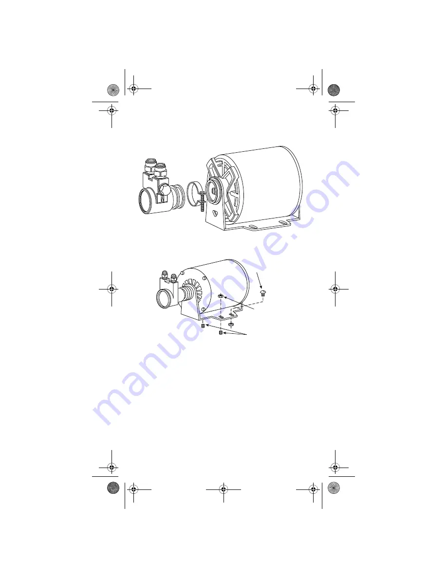
Additional Glycol Circulating Pump and
Motor Kit
Pump and Motor Kit
Motor Installation
NOTE: Only two fasteners required.
Carriage Bolts
(Later Units)
Mounting Studs
(Early Units)
5/16" - 18 Hex Nut
STH13_Tech.book Page 68 Wednesday, September 15, 2010 3:20 PM


