


Reference
Only
INTRODUCTION
18000 SERIVCE/MAINTENANCE MANUAL
1-24
Published 12-05-17, Control # 035-23
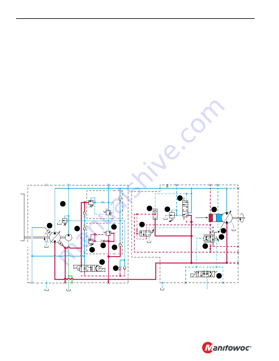
Each variable displacement motor, except travel, begins
operation at maximum displacement (high torque, low
speed) and shifts to minimum displacement (low torque, high
speed) if torque requirement is low. The motor remains in
maximum displacement until servo PC valve (10) receives a
command from PCP valve (11) to direct system pressure and
flow from shuttle valve (12) to minimum displacement side of
servo cylinder (13) that shifts motor. As PCP valve opens in
proportion to output voltage received from the node
controller, pilot line pressure is directed to shift servo PC
valve. After overcoming adjustable valve spring (14) and
valve spring (15), servo PC valve shifts and directs fluid to
stroke motor at minimum displacement output. If the load at
the motor shaft increases, force on adjustable valve spring
increases. This shifts servo PC valve to de-stroke the motor
to maximum displacement for safe load handling.
The load drums and boom hoist motors also have a PCOR
(Pressure Compensating Over-Ride) valve (16) that is
enabled when system pressure of 4,930 psi (340 bar) is
reached. When system pressure exceeds the PCOR setting,
the valve shifts to direct flow from shuttle valve into maximum
displacement side of servo cylinder. The PCOR valve over-
rides the command from servo PC valve, increasing motor
displacement and output torque and reducing output speed.
When PCOR valve closes, control of the motor returns to
servo PC valve.
The travel motor servo is opposite of other system motors.
The travel variable displacement motors begin operation at
minimum displacement (low torque, high speed). The motor
shifts to maximum displacement (high torque, low speed)
when starting torque is required and back to minimum
displacement when in motion if load is below a preset
pressure of 3770 psi (270 bar). Depending on motor system,
servo uses internally or externally supplied pressure to
perform the shifting operation. Servo control fluid is supplied
from high-pressure line of motor port “A” or “B” and shifts
shuttle valve and servo control valve before entering servo
cylinder.
Continuous changing of closed-loop fluid occurs through
leakage in pumps, motors, and loop flushing valves. Motor
case fluid drainage lubricates the motor and provides a re-
circulation of hydraulic fluid to control heat in closed-loop
system. Motors also have an internal or external loop
flushing (purge) system that consists of control valve (17)
and relief valve (18). If system pressure is above 200 psi (14
bar), loop flushing removes 4 gallons per minute (15 l/m) of
hot fluid from system for added cooling and purification. If
system pressure is under 200 psi (14 bar) loop flush is
disabled.
Engine Controls
See engine manufacturer’s manual for instructions.
The engine is started and stopped with engine key switch.
Engine rpm is controlled with the hand throttle or foot throttle
and is monitored with an AC magnetic sensor. Node-1
controller, engine node-0 controller, and engine control
(23 bar)
340 PSI
T2
T3
A
MAX.
P
U
M
P
D
R
IV
E
B
B
A
A
D
C
E
G
F
D
OUTPUT
INPUT
PUMP
MOTOR
B
A
M8
M7
M3
M4
M6
L2
M9
M2
M5
M1
11
4
6
18
13
5
10
9
15
14
7
16
12
17
2
1
8
3
FIGURE 1-18
DISP.
T1
18CSM1-117
Summary of Contents for 18000
Page 1: ...R e f e r e n c e O n l y Service Maintenance Manual Manitowoc 18000 ...
Page 2: ...R e f e r e n c e O n l y ...
Page 4: ...R e f e r e n c e O n l y THE ORIGINAL LANGUAGE OF THIS PUBLICATION IS ENGLISH ...
Page 210: ...R e f e r e n c e O n l y NOTES SKETCHES AND PHOTOGRAPHS ...
Page 315: ...R e f e r e n c e O n l y ...
Page 316: ...R e f e r e n c e O n l y ...