


Reference
Only
Manitowoc
Published 12-05-17, Control # 035-23
1-23
18000 SERIVCE/MAINTENANCE MANUAL
INTRODUCTION
1
Basic Operation
for the following procedure.
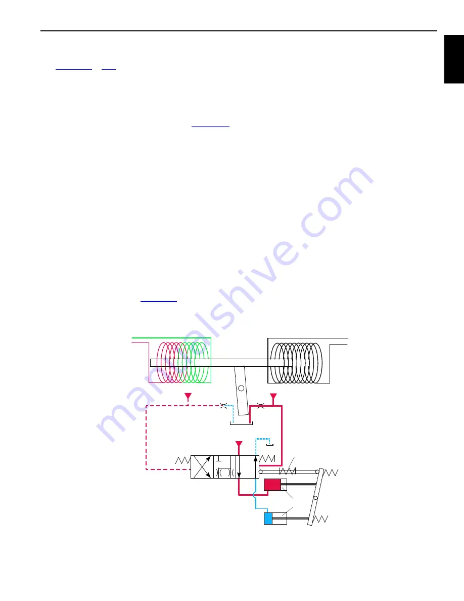
When a control handle is moved from neutral, an input
voltage in the handle command direction is sent to node-1
controller. The component node controller sends a variable
zero to 24 volt output that is divided by a resistor and applied
to pump external EDC (Electrical Displacement Control).
The output current magnetizes an armature (
and starts to block one of the orifice ports, depending on
command direction. Blockage of flow at exhaust side of right
orifice port causes a pressure difference across spool. This
pressure difference overcomes the resistance of spool
spring and moves the spool proportionally to pressurize top
servo pistons. The fluid from bottom servo pistons is routed
to tank. This tilts the swashplate, stroking the pump in
selected command direction. As swashplate tilts, chamber
spring is pulled in the opposite direction of spool with linkage.
This centers and maintains spool in a neutral position until
the 16 psi (1 bar) chamber spring pressure is reached.
In travel pumps, the pressure relief and pressure-limiting
sections of multifunction valves respond when relief
pressure is reached. The pressure limiting function of travel
pumps is set not to exceed 6090 psi (420 bar). If travel pump
pressure exceeds preset pressure limit, pumps de-stroke to
prevent overheating of system fluid.
Hydraulic fluid pressure overcomes spring resistance in
pressure limiting relief valve (1,
), shifting spool to
open a line for fluid pressure. Servo check valve (2) is spring
loaded with an opening pressure of 750 psi (52 bar).
Hydraulic fluid from pressure limiting relief valve flows
through exhaust port of displacement control valve (3). The
exhaust port has a restricted orifice that develops pressure
for servo control cylinder (4) to pressurize and de-stroke
pump to limit system pressure. When rapid loading produces
pressure spikes, system relief valve (5) shifts. This allows
high-pressure fluid to return to tank through charge pump
relief valve (6). Alternatively, fluid transfers to low-pressure
side of closed-loop system through charge flow make-up
check valve (7).
In other system pumps, pressure limiting is controlled
through relief valve section of multifunction valves only. Flow
control orifice (8) is removed from pump EDC. Servo check
valves are removed from pump and lines to servo control
cylinders are plugged. These changes permit the pump to
react quicker to control handle commands.
The pressure limiting relief valve (1) serves as pilot valve to
open system relief valve (5) when desired relief pressure
setting is reached. For example, if a pressure imbalance
occurs on both sides of flow restrictor (9), pressure limiting
valve opens and system relief valve relieves system
pressure. Hydraulic fluid is directed to tank through relief
valve (7) or the flow is transferred to low-pressure side of
system through the make-up check valve (8).
Pump displacement depends on engine driven pump speed
through pump drive and swashplate tilt angle. The engine
provides power for work, while the swashplate tilt angle
provides speed control. Engine speed is set and controlled
with hand or foot engine throttle.
SWASHPLATE
SERVO PISTONS
PILOT PRESSURE
7
ORIFICE
PORT
MODULATION
ORIFICE
PORT
SPRING
CONTROL VOLTAGE
ARMATURE
SPOOL
PILOT PRESSURE
PILOT PRESSURE
SPOOL
SPRING
FROM CONTROLLER
CONTROL VOLTAGE
FROM CONTROLLER
FIGURE 1-17
18CSM1-116
Summary of Contents for 18000
Page 1: ...R e f e r e n c e O n l y Service Maintenance Manual Manitowoc 18000 ...
Page 2: ...R e f e r e n c e O n l y ...
Page 4: ...R e f e r e n c e O n l y THE ORIGINAL LANGUAGE OF THIS PUBLICATION IS ENGLISH ...
Page 210: ...R e f e r e n c e O n l y NOTES SKETCHES AND PHOTOGRAPHS ...
Page 315: ...R e f e r e n c e O n l y ...
Page 316: ...R e f e r e n c e O n l y ...