
TPM 083/12
12
Park Allé 366, DK-2605 Brondby
Telefon 70 20 19 11; E-mail:[email protected]
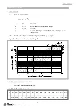
8. Noise data
8.1.
Level of acoustic output corrected with filter A.
L
WA
[dB(A)] level of acoustic output corrected with filter A
L
W1
[dB]
level of acoustic output L
W1
related to the 1 m
2
section (see Tab. 8.3.1.)
S
[m
2
]
effective area of the damper
K
A
[dB]
correction to the weight filter A (see Tab. 8.3.2.)
L
WA
= L
W1
+ 10 log(S) + K
A
8.2.
Level of acoustic output in octave ranges.
L
Woct
[dB]
spectrum of acoustic output in octave range
L
W1
[dB]
level of acoustic output L
W1
related to the 1 m
2
section (see Tab. 8.3.1.)
S
[m
2
]
effective area of the damper
L
rel
[dB]
relative level expressing the shape of the spectrum (see Tab. 8.3.3.)
L
Woct
= L
W1
+ 10 log(S) + L
rel
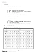
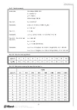
8.3.
Table of acoustics values
Tab. 8.3.1. Level of acoustic output L
W1
related to the 1 m
2
section
[-]
w [m.s
-1
]
0,1
0,2
0,3
0,4
0,6
0,8
1
1,5
2
2,5
3
3,5
2
9,0
11,5 14,7 16,9 20,1
22,3
24,1
27,2
29,4
31,2
32,6
33,8
3
16,7 22,1 25,3 27,5 30,7
32,9
34,6
37,8
40,0
41,7
43,2
44,4
4
24,2 29,6 32,8 35,0 38,1
40,4
42,1
45,3
47,5
49,2
50,7
51,9
5
30,0 35,4 38,6 40,8 44,0
46,2
47,9
51,1
53,3
55,1
56,5
57,7
6
34,8 40,2 43,3 45,6 48,7
51,0
52,7
55,8
58,1
59,8
61,2
62,4
7
38,8 44,2 47,3 49,6 52,7
55,0
56,7
59,9
62,1
63,8
65,2
66,4
8
42,3 47,7 50,8 53,1 56,2
58,4
60,2
63,3
65,6
67,3
68,7
69,9
9
45,4 50,7 53,9 56,1 59,3
61,5
63,3
66,4
68,6
70,4
71,8
73,0
10
48,1 53,5 56,6 58,9 62,0
64,3
66,0
69,1
71,4
73,1
74,5
75,7
11
50,6 56,0 59,1 61,4 64,5
66,7
68,5
71,6
73,9
75,6
77,0
78,2
12
52,8 58,2 61,4 63,6 66,8
69,0
70,7
73,9
76,1
77,9
79,3
80,5


