

TPM 083/12
7
Park Allé 366, DK-2605 Brondby
Telefon 70 20 19 11; E-mail:[email protected]
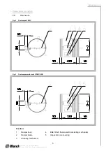
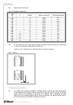
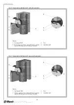
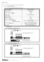
Fig. 5
Placement of the openings in the wall
min. 75
min
. 7
5
min. 200
4.4.
The control mechanism has to be protected (covered) against damage and pollution during
installation process.
4.5.
All fire dampers has to be closed during installation process. The damper body should not be
deformed in the course of bricking in. Once the damper is built in, its blade should not grind on
the damper body during opening or closing.
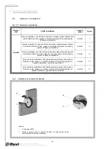
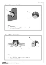
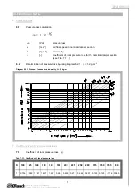
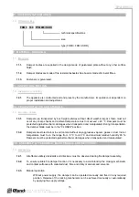
4.7.
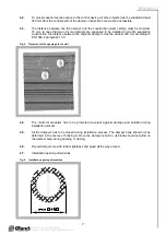
Installation opening dimensions
4.2.
To provide needed access space to the control device, all other objects must be situated at least
350 mm from the control parts of the damper. Inspection hole must be accessible.
4.3.
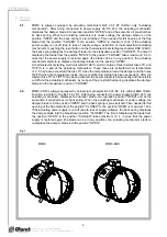
The distance between the fire damper and the construction (wall, ceiling) must be minimum
75 mm. In case that two or more dampers are supposed to be installed in one fire separating
construction, the distance between the adjacent dampers must be at least 200 mm according to
EN 1366-2 paragraph 13.5.
Fig. 6
Installation opening dimensions
4.6.
Round dampers are with rubber tightness and glued all the way around.


