

TPM 083/12
4
Park Allé 366, DK-2605 Brondby
Telefon 70 20 19 11; E-mail:[email protected]
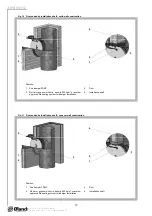
2. Design
2.1.
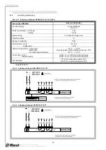
FDMC is always equipped by actuating mechanism BLF 24-T-ST (further only "actuating
mechanism"). After being connected to power supply AC/DC 24V, the actuating mechanism
displaces the damper blade into operation position "OPEN" and at the same time it pre-stretches
its back spring. When the actuating mechanism is under voltage, the damper blade is in the
position "OPEN" and the back spring is pre-stretched. Time needed for full opening of the flap
blade from the position "CLOSED" to the position "OPEN" is maximum 140s. If the actuating
power supply is cut off (due to loss of supply voltage, activation of thermoelectrical actuating
mechanism or pushing the reset button on the thermoelectrical starting mechanism BAE 72B-S),
the back spring displaces the damper blade into the breakdown position "CLOSED". The time of
displacing the blade from the position "OPEN" to the position "CLOSED" takes maximum 16 s. In
case that the power supply is restored again (the blade can be in any position), the actuating
mechanism starts to re-displace the damper blade into the position "OPEN".
A thermoelectrical starting mechanism BAE 72B-S, which contains three thermal fuses Tf1 and
Tf2/Tf3, is a part of the actuating mechanism. These fuses are activated when temperature
+72 °C has been exceeded (the fuse Tf1 when the temperature around the damper and the fuses
Tf2/Tf3 when the temperature inside the air-conditioning piping has been exceeded). After the
thermal fuse Tf1 or Tf2/Tf3 has been activated, the power supply is permanently and irreversibly
cut off and the actuating mechanism, by means of the pre-stretched spring, displaces the damper
blade into the breakdown position "CLOSED".
2.2.
FDMC-SRD is always equipped by actuating mechanism BLF 24-ST. It is without BAE 72B-S.
Function is similar to the BLF 24-T-ST. After being connected to power supply AC/DC 24V, the
actuating mechanism displaces the damper blade into operation position "OPEN" and at the
same time it pre-stretches its back spring. When the actuating mechanism is under voltage, the
damper blade is in the position "OPEN" and the back spring is pre-stretched. Time needed for full
opening of the flap blade from the position "CLOSED" to the position "OPEN" is maximum 140s.
If the actuating power supply is cut off (due to loss of supply voltage), the back spring displaces
the damper blade into the breakdown position "CLOSED". The time of displacing the blade from
the position "OPEN" to the position "CLOSED" takes maximum 16 s. In case that the power
supply is restored again (the blade can be in any position), the actuating mechanism starts to
re-displace the damper blade into the position "OPEN".
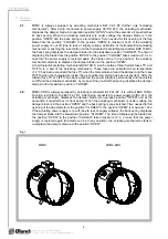
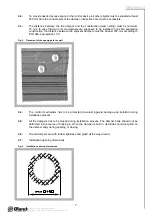
Fig. 1
FDMC
FDMC-SRD


