
TPM 083/12
3
Park Allé 366, DK-2605 Brondby
Telefon 70 20 19 11; E-mail:[email protected]
II. GENERAL INFORMATION
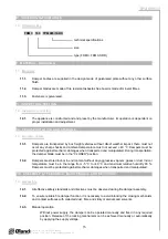
1. Description
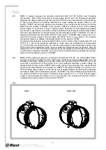
1.1.
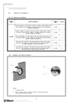
Fire dampers are shutters in piping systems of air-conditioning devices that prevent spreading
the fire and combustion products from one fire segment to the other one by means of closing the
air piping in the points of fire separating constructions.
1.4.
The damper is sealed with a silicon packing against smoke penetration after closing the blade. At
the same time, the damper blade is bed in a material which enlarges its capacity and air proofs
the air duct.
1.3.
Dampers blade automatically closes air duct using an actuating mechanism back spring. The
back spring of the actuating mechanism is started when the thermoelectrical starting mechanism
BAE 72B-S is activated, when a reset button on BAE 72B-S is pushed or when a power supply
of the actuating mechanism is stopped (for FDMC-SRD only when the power supply of the
actuating mechanism is stopped).
1.2.
Dampers are in all variants classified as EI 60 ve, ho (i o) S acc. EN 13501-3 and tested acc.
EN 1366-2.
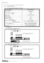
1.5.
Dampers have one inspection hole, since the shutting device and the inspection hole can be set
into the most advantageous position (with respect to the operation and manipulation with the
control device).
1.6.
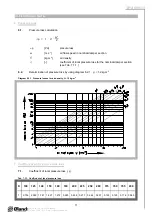
Exact damper function is provided under the following conditions:
a) Maximum air circulation speed: 12 m.s
-1
Maximum pressure difference: 1200 Pa
b) Dampers could be displaced into position “CLOSED” only in case that ventilator, or Air
Handling Unit is switched off. The goal is the securing of proper closing and safe
function of Fire Damper in case of Fire.
c) The air circulation in the whole damper section must be secured as steady on whole
surface.
1.7.
Dampers are designed for macroclimatic areas with mild climate according to EN 60 721-3-3.
1.8.
Dampers are suitable for systems without abrasive, chemical and adhesive particles.
1.9.
Temperature in the place of installation is permitted to range from - 20°C to + 50°C.
1.11.
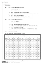
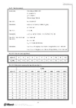
In this document are used next signs and units.
Key :
w
[m.s
-1
]
air velocity
p
[Pa]
pressure loss
L
w
[dB]
level of acoustic output
[ ]
pressure loss coefficient
[kg.m
-3
]
density
A,B, a, c,
e, f
[mm]
dimension
S [m
2
]
area
1.10.
If is not noticed other way, all dimensions and weight are in millimeters and kilograms.