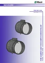

TPM 083/12
15
Park Allé 366, DK-2605 Brondby
Telefon 70 20 19 11; E-mail:[email protected]
11. Material
V. MATERIAL, FINISHING
11.1.
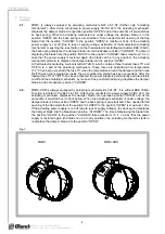
Damper bodies are supplied in the design made of galvanized plate without any other surface
finish.
11.2.
Damper blades are made of fire resistant asbestos free boards made of mineral fibres.
11.3.
Fasteners
is
galvanized.
VI. INSPECTION, TESTING
12. Inspection, testing
12.1.
The appliance is constructed and and preset by the manufacturer, its operation is dependent on
proper installation and adjustment.
IV. ORDERING INFORMATION
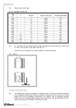
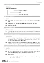
10. Ordering key
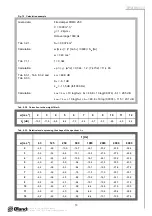
technical specifications
size
type (FDMC, FDMC-SRD)
FDMC
180 TPM 083/12-DK
VIII. ASSEMBLY, ATTENDANCE, MAINTENANCE AND REVISIONS
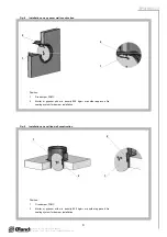
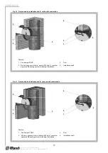
14. Assembly
14.1.
All effective safety standards and directives must be observed during fire damper assembly.
14.2.
To ensure reliable fire damper function it is necessary to avoid blocking the closing mechanism
and contact surfaces with collected dust, fibre and sticky materials and solvents.
13. Logistic terms
13.1.
Dampers are transported by box freight vehicles without direct weather impact, there must not
occur any sharp shocks and ambient temperature must not 40 °C. Dampers must be
protected against mechanic damages when transported and manipulated. During transportation,
the damper blade must be in the "CLOSED" position.
VII. TRANSPORTATION AND STORAGE
13.2.
Dampers are stored indoor in environment without any aggressive vapours, gases or dust. Indoor
temperature must be in the range from -5 °C to +40 °C and maximum relative humidity 80 %.
Dampers must be protected against mechanic damages when transported and manipulated.
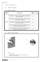
14.3.
Manual
operation
Without power supply, the damper can be operated manually and fixed in any required
position. Release of the locking mechanism can be achieved manually or automatically
by applying the supply voltage.


