
TPM 083/12
6
Park Allé 366, DK-2605 Brondby
Telefon 70 20 19 11; E-mail:[email protected]
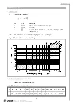
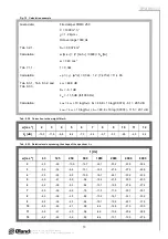
Tab. 3.2.1. Weight and effective area
Size
D
a
Weight
Effective area
S
ef
[m
2
]
Actuating mechanism
100
-
3,1
0,0036
BLF
125
-
3,4
0,0068
BLF
140
-
3,6
0,0092
BLF
150
-
3,7
0,0109
BLF
160
-
3,8
0,0129
BLF
180
-
4,1
0,0172
BLF
200
-
4,4
0,0222
BLF
225
-
4,7
0,0293
BLF
250
9
5,5
0,0374
BLF
280
24
6,0
0,0484
BLF
315
41,5
6,6
0,0630
BLF
350
59
7,0
0,0793
BLF
355
61,5
7,3
0,0821
BLF
400
84
8,2
0,1065
BLF
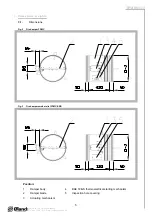
3.2.
Weight and effective area
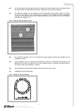
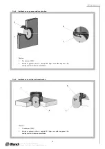
4. Placement and Assembly
4.1.
Fire dampers are suitable for installation in arbitrary position in vertical and horizontal passages
of fire separating constructions. Damper assembly procedures must be done so as all load
transfer from the fire separating constructions to the damper body is absolutely excluded.
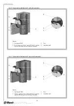
Back-to-back air-conditioning piping must be hung or supported so as all load transfer from the
back-to-back piping to the damper is absolutely excluded.
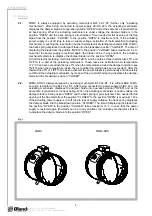
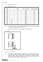
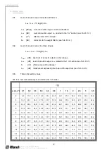
3.3.
For fire damper the open damper blade overlaps the damper body from dimension 250 by the
“a” value. These values are specified in the Tab. 3.2.1
Value has to be respected when projecting related air-conditioning piping.
Fig. 4
Value “a”


