background image

TPM 083/12

16

Park Allé 366, DK-2605 Brondby
Telefon 70 20 19 11; E-mail:[email protected]

The producer reserves the right for innovations of the product. For actual product information see

www.mandik.com

MANDÍK a.s.
Dob

ř

íšská 550

26724 Hostomice

Č

eská Republika

Tel.: +420 311 706 706
Fax: +420 311 584 810, 311 584 382
E-Mail: [email protected]
www.mandik.com

Your distributor 

15. Entry into service and revisions

15.1. 


Before entering the dampers into operation after assembly and after sequential revisions, checks 
and functionality tests of all designs including operation of the electrical components must be
done. After entering into operation, these revisions must be done according to requirement set
by national regulations.

15.1.1. 

  In case that dampers are found unable to serve for their function for any cause, it must be clearly

marked. The operator is obliged to ensure so that the damper is put into condition in which it is
able to function and meanwhile he is obliged to provide the fire protection another appropriate
way.

15.2. 


Before entering the dampers into operation after their assembly and by sequential checks, the
 following checks must be carried out.

15.2.1. 

  Visual inspection of proper damper integration, inside damper area, damper blade, contact

surfaces and silicon sealing.
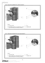
15.2.2. 

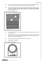
  Inspection hole disassembly: release the covering lid by unscrewing screws. Then tilt remove lid

from its original position.

15.1.2. 

  Results of regular checks, imperfections found and all-important facts connected with the damper

function must be recorded in the "FIRE BOOK" and immediately reported to the operator.

15.2.3. 

  Check of blade displacement into the breakdown position "CLOSED" can be done after cutting

off the actuating mechanism supply (e.g. by pressing the RESET button at the thermoelectrical
starting mechanism BAE 72B-S - only FDMC or cutting off the supply from ELECTRICAL FIRE
SIGNALISATION). Check of blade displacement back into the "OPEN" position can be done after
restoration of power supply (e.g. By releasing the RESET button - only FDMC or restoration of
supply from ELECTRICAL FIRE SIGNALISATION).

Summary of Contents for FDMC

Page 1: ...FDMC FDMC SRD TPM 083 12 DK VALID FROM 15 1 2012 FIRE DAMPER AND FIRE DAMPER SMOKE RELIEF...

Page 2: ...ription 3 2 Design 4 3 Dimensions weights 5 4 Placement and Assembly 6 5 Statement of installations 8 III TECHNICAL DATA 9 6 Pressure loss 9 7 Coefficient of local pressure loss 10 8 Noise data 10 9 E...

Page 3: ...N 13501 3 and tested acc EN 1366 2 1 5 Dampers have one inspection hole since the shutting device and the inspection hole can be set into the most advantageous position with respect to the operation a...

Page 4: ...of the actuating mechanism These fuses are activated when temperature 72 C has been exceeded the fuse Tf1 when the temperature around the damper and the fuses Tf2 Tf3 when the temperature inside the...

Page 5: ...1 E mail oeland oeland dk Position 1 Damper body 4 BAE 72B S thermoelectrical starting mechanism 2 Damper blade 5 Inspection hole covering 3 Actuating mechanism Fig 2 Fire damper FDMC Fig 3 Fire dampe...

Page 6: ...a 4 Placement and Assembly 4 1 Fire dampers are suitable for installation in arbitrary position in vertical and horizontal passages of fire separating constructions Damper assembly procedures must be...

Page 7: ...mper body during opening or closing 4 7 Installation opening dimensions 4 2 To provide needed access space to the control device all other objects must be situated at least 350 mm from the control par...

Page 8: ...tallation EIS 60 8 Damper installed on a solid ceiling construction Space between damper and ceiling is filled by mortar gypsum or another approved fire sealing system for damper installation EIS 60 9...

Page 9: ...min density 800 kg m3 or another approved fire sealing system for damper installation Fig 8 Installation on a gypsum wall construction 2 1 2 1 Fig 9 Installation on a ceiling wall construction 1 2 2 1...

Page 10: ...t solid wall construction 4 Position 1 Fire damper FDMC 3 Duct 2 Mortar or gypsum with min density 800 kg m3 or another approved fire sealing system for damper installation 4 Installation shaft 3 1 2...

Page 11: ...oss for the nominal damper section see Tab 7 1 1 III TECHNICAL DATA 6 2 Determination of pressure loss by using diagram 6 2 1 1 2 kg m 3 Diagram 6 2 1 Pressure losses for air density 1 2 kg m 3 7 1 Co...

Page 12: ...see Tab 8 3 3 LWoct LW1 10 log S Lrel 8 3 Table of acoustics values Tab 8 3 1 Level of acoustic output LW1 related to the 1 m2 section w m s 1 0 1 0 2 0 3 0 4 0 6 0 8 1 1 5 2 2 5 3 3 5 2 9 0 11 5 14 7...

Page 13: ...l 48 8 10 log 0 0374 11 5 23 1 dB Tab 8 3 2 Correction to the weight filter A w m s 1 2 3 4 5 6 7 8 9 10 11 12 KA dB 15 0 11 8 9 8 8 4 7 3 6 4 5 7 5 0 4 5 4 0 3 6 Tab 8 3 3 Relative level expressing t...

Page 14: ...oring holding 5 W 2 5 W Dimensioning 7 VA Imax 5 8 A 5 ms Protection Class III Degree of protection IP 54 Running time motor spring return 40 75 s 20 s Ambient Temperature normal duty safety duty non...

Page 15: ...e fire damper function it is necessary to avoid blocking the closing mechanism and contact surfaces with collected dust fibre and sticky materials and solvents 13 Logistic terms 13 1 Dampers are trans...

Page 16: ...ile he is obliged to provide the fire protection another appropriate way 15 2 Before entering the dampers into operation after their assembly and by sequential checks the following checks must be carr...

Reviews: