background image

TPM 083/12

13

Park Allé 366, DK-2605 Brondby
Telefon 70 20 19 11; E-mail:[email protected]

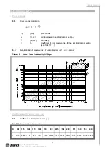
Fig. 12  Calculation example

Given data:

Fire damper FDMC 250

V = 1000 m

3

.h

-1

   = 1,2 kg.m

-3

Octave range 1000 Hz

Tab. 3.2.1.

S

ef

 = 0,0374 m

2

Calculation :

w [m.s

-1

] = (V [m

3

.h

-1

] / 3600) / S

ef

 [m

2

]

w = 7,43 m.s

-1


Tab. 7.1.1.

   = 0,344

Calculation :

  p =   .   . (w

2

/2) = 0,344 . 1,2 . (7,43

2

/2) = 11,4 Pa

Tab. 8.3.1., Tab. 8.3.2. and 
Tab. 8.3.3.

L

W1

 = 48,8 dB

K

A

 = - 6,1 dB

L

rel

 = -11,5 dB (for1000 Hz)

Calculation :

L

WA

 = L

W1

 + 10 log(S

ef

) + K

A

 = 48,8 + 10 log(0,0374) - 6,1 = 28,5 dB

L

Woct

 = L

W1

 + 10 log(S

ef

) + L

rel

 = 48,8 + 10 log(0,0374) - 11,5 = 23,1 dB  

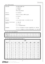
Tab. 8.3.2.  Correction to the weight filter A

w [m.s

-1

]

2

3

4

5

6

7

8

9

10

11

12

K

A

 [dB]

-15,0

-11,8

-9,8

-8,4

-7,3

-6,4

-5,7

-5,0

-4,5

-4,0

-3,6

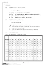
Tab. 8.3.3.  Relative level expressing the shape of the spectrum L

rel

 f [Hz]

w [m.s

-1

]

 63  

 125  

 250  

 500  

 1000  

 2000  

 4000  

 8000  

 2  

-4,5  

-6,9  

 -10,9  

-16,7  

-24,1  

-33,2  

-43,9  

-56,4  

 3  

-3,9  

-5,3  

-8,4  

-13,1  

-19,5  

-27,6  

-37,4  

-48,9  

 4  

-3,9  

-4,5  

-6,9  

-10,9  

-16,7  

-24,1  

-33,2  

-43,9  

 5  

-4,0  

-4,1  

-5,9  

-9,4  

-14,6  

-21,5  

-30,0  

-40,3  

 6  

-4,2  

-3,9  

-5,3  

-8,4  

-13,1  

-19,5  

-27,6  

-37,4  

 7  

-4,5  

-3,9  

-4,9  

-7,5  

-11,9  

-17,9  

-25,7  

-35,1  

 8  

-4,9  

-3,9  

-4,5  

-6,9  

-10,9  

-16,7  

-24,1  

-33,2  

 9  

-5,2  

-3,9  

-4,3  

-6,4  

-10,1  

-15,6  

-22,7  

-31,5  

 10  

-5,5  

-4,0  

-4,1  

-5,9  

-9,4  

-14,6  

-21,5  

-30,0  

 11  

-5,9  

-4,1  

-4,0  

-5,6  

-8,9  

-13,8  

-20,4  

-28,8  

 12  

-6,2  

-4,3  

-3,9  

-5,3  

-8,4  

-13,1  

-19,5  

-27,6  

Summary of Contents for FDMC

Page 1: ...FDMC FDMC SRD TPM 083 12 DK VALID FROM 15 1 2012 FIRE DAMPER AND FIRE DAMPER SMOKE RELIEF...

Page 2: ...ription 3 2 Design 4 3 Dimensions weights 5 4 Placement and Assembly 6 5 Statement of installations 8 III TECHNICAL DATA 9 6 Pressure loss 9 7 Coefficient of local pressure loss 10 8 Noise data 10 9 E...

Page 3: ...N 13501 3 and tested acc EN 1366 2 1 5 Dampers have one inspection hole since the shutting device and the inspection hole can be set into the most advantageous position with respect to the operation a...

Page 4: ...of the actuating mechanism These fuses are activated when temperature 72 C has been exceeded the fuse Tf1 when the temperature around the damper and the fuses Tf2 Tf3 when the temperature inside the...

Page 5: ...1 E mail oeland oeland dk Position 1 Damper body 4 BAE 72B S thermoelectrical starting mechanism 2 Damper blade 5 Inspection hole covering 3 Actuating mechanism Fig 2 Fire damper FDMC Fig 3 Fire dampe...

Page 6: ...a 4 Placement and Assembly 4 1 Fire dampers are suitable for installation in arbitrary position in vertical and horizontal passages of fire separating constructions Damper assembly procedures must be...

Page 7: ...mper body during opening or closing 4 7 Installation opening dimensions 4 2 To provide needed access space to the control device all other objects must be situated at least 350 mm from the control par...

Page 8: ...tallation EIS 60 8 Damper installed on a solid ceiling construction Space between damper and ceiling is filled by mortar gypsum or another approved fire sealing system for damper installation EIS 60 9...

Page 9: ...min density 800 kg m3 or another approved fire sealing system for damper installation Fig 8 Installation on a gypsum wall construction 2 1 2 1 Fig 9 Installation on a ceiling wall construction 1 2 2 1...

Page 10: ...t solid wall construction 4 Position 1 Fire damper FDMC 3 Duct 2 Mortar or gypsum with min density 800 kg m3 or another approved fire sealing system for damper installation 4 Installation shaft 3 1 2...

Page 11: ...oss for the nominal damper section see Tab 7 1 1 III TECHNICAL DATA 6 2 Determination of pressure loss by using diagram 6 2 1 1 2 kg m 3 Diagram 6 2 1 Pressure losses for air density 1 2 kg m 3 7 1 Co...

Page 12: ...see Tab 8 3 3 LWoct LW1 10 log S Lrel 8 3 Table of acoustics values Tab 8 3 1 Level of acoustic output LW1 related to the 1 m2 section w m s 1 0 1 0 2 0 3 0 4 0 6 0 8 1 1 5 2 2 5 3 3 5 2 9 0 11 5 14 7...

Page 13: ...l 48 8 10 log 0 0374 11 5 23 1 dB Tab 8 3 2 Correction to the weight filter A w m s 1 2 3 4 5 6 7 8 9 10 11 12 KA dB 15 0 11 8 9 8 8 4 7 3 6 4 5 7 5 0 4 5 4 0 3 6 Tab 8 3 3 Relative level expressing t...

Page 14: ...oring holding 5 W 2 5 W Dimensioning 7 VA Imax 5 8 A 5 ms Protection Class III Degree of protection IP 54 Running time motor spring return 40 75 s 20 s Ambient Temperature normal duty safety duty non...

Page 15: ...e fire damper function it is necessary to avoid blocking the closing mechanism and contact surfaces with collected dust fibre and sticky materials and solvents 13 Logistic terms 13 1 Dampers are trans...

Page 16: ...ile he is obliged to provide the fire protection another appropriate way 15 2 Before entering the dampers into operation after their assembly and by sequential checks the following checks must be carr...

Reviews: