6
7
8
Replacing cylinder liners
114
Installing cylinder liners
Fig. 6
Insert dry new O-rings for the lower seal (144x4)
into the crankcase.
Fig. 7
Insert new O-rings for the upper seal (138x2) into
the grooves on the cylinder liner.
Do not overstretch the O-rings.
Fig. 8
Apply thin coat of engine oil to cylinder liner in the
area of the upper and lower O-ring.
Apply thin coat of engine oil to lower O-rings in the
crankcase.
Insert cylinder liners into crankcase and push them
down by hand.
Place clean metal plate on liner and exert uniform
downward pressure until the liner is seated in the
crankcase recess.
If a perceptible resistance can be felt in this oper-
ation, the O-rings are no longer in their proper
place.
Reposition O-rings and insert cylinder liner again.
Note:
No grease or sealing agents of any kind
must be used for installing cylinder liners and
O-rings.
Note:
After fitting the cylinderliners ensure that the
O-rings are in the correct position by checking
the liner protrusion with special tool. Use
special tool, see page 132 as follows:
Position press-on measuring plate (1) with
turned collar facing the liner using 2 fitting
sleeves to centre plate.
Tighten 4 bolts (2) (improvised: collar bolt
51.90020-0270, length shortened to 90 mm)
on the press-on measuring plate in stages and
crosswise to 40 Nm.
Set dial gauge combination above press-on
plate to “0” under preload relative to the crank-
case.
Measure cylinder liner protrusion at least at
four points.
3574
3575
3576
Summary of Contents for D 2866 LE 401
Page 1: ......
Page 17: ...Engine views D 2866 LE401 16...
Page 18: ...Engine views D 2866 LE401 17...
Page 19: ...Cross section of engine 18...
Page 20: ...Longitudinal section 19...
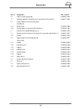
Page 124: ...123 Special tools...
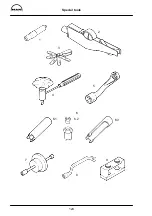
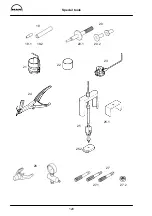
Page 125: ...Special tools 124 2 3 4 5 6 7 9 1 8 6 1 6 2 6 3...
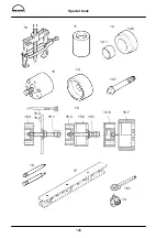
Page 129: ...Special tools 128 21 22 23 25 25 2 24 25 1 26 27 1 27 2 27 20 1 19 2 19 1 20 2 19 20...
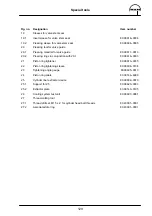
Page 131: ...Special tools 130 29 28 30...
Page 138: ......


