5
6
7
8
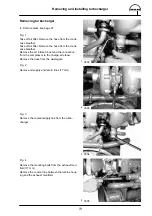
Removing and installing cylinder head
80
Fig. 5
Take out push rods.
Fig. 6
Remove cylinder head bolts in reverse order of
tightening.
Note:
Use reinforced socket (screw–driving ma-
chine) to loosen and tighten the cylinder
head bolts.
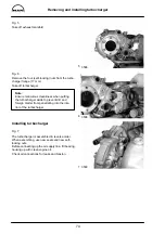
Fig. 7
Remove the mounting bolts from the intake and
exhaust pipes for the respective cylinder head.
Also remove those intake and exhaust pipe bolts,
which are adjacent to the respective cylinder head.
This will reduce the tension on the cylinder head,
and the head can be taken off more easily.
Fig. 8
Take off cylinder head and cylinder head gasket.
Check whether cylinder head sealing face and cyl-
inder block are plane using a straight edge.
Non-plane cylinder heads can be remilled 1 mm.
Notice specified projection of injection nozzles and
valve recess (see ”Engineering
S
Data
S
Setting
values”).
Note:
Check cylinder heads for cracks.
3516
3517
3518
3705
Summary of Contents for D 2866 LE 401
Page 1: ......
Page 17: ...Engine views D 2866 LE401 16...
Page 18: ...Engine views D 2866 LE401 17...
Page 19: ...Cross section of engine 18...
Page 20: ...Longitudinal section 19...
Page 124: ...123 Special tools...
Page 125: ...Special tools 124 2 3 4 5 6 7 9 1 8 6 1 6 2 6 3...
Page 129: ...Special tools 128 21 22 23 25 25 2 24 25 1 26 27 1 27 2 27 20 1 19 2 19 1 20 2 19 20...
Page 131: ...Special tools 130 29 28 30...
Page 138: ......


