5
6
7
Removing and installing turbocharger
74
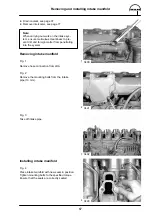
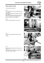
Fig. 5
Take off exhaust manifold.
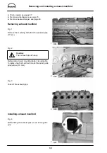
Fig. 6
Remove the four (self–locking) nuts from the turbo-
charger flange (17 mm).
Take off turbocharger.
Note:
Ensure meticulous cleanliness when putting
the turbocharger aside to prevent dirt and
foreign matter from penetrating into the inte-
rior of the turbocharger.
Installing turbocharger
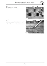
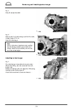
Fig. 7
The turbocharger is assembled in reverse order.
When assembling, use new seals and new self–
locking nuts.
Before connecting up the oil supply line, fill bearing
housing up with clean engine oil.
Check all connections for leaks and tension.
3506
3508
3509
Summary of Contents for D 2866 LE 401
Page 1: ......
Page 17: ...Engine views D 2866 LE401 16...
Page 18: ...Engine views D 2866 LE401 17...
Page 19: ...Cross section of engine 18...
Page 20: ...Longitudinal section 19...
Page 124: ...123 Special tools...
Page 125: ...Special tools 124 2 3 4 5 6 7 9 1 8 6 1 6 2 6 3...
Page 129: ...Special tools 128 21 22 23 25 25 2 24 25 1 26 27 1 27 2 27 20 1 19 2 19 1 20 2 19 20...
Page 131: ...Special tools 130 29 28 30...
Page 138: ......


