background image


13 

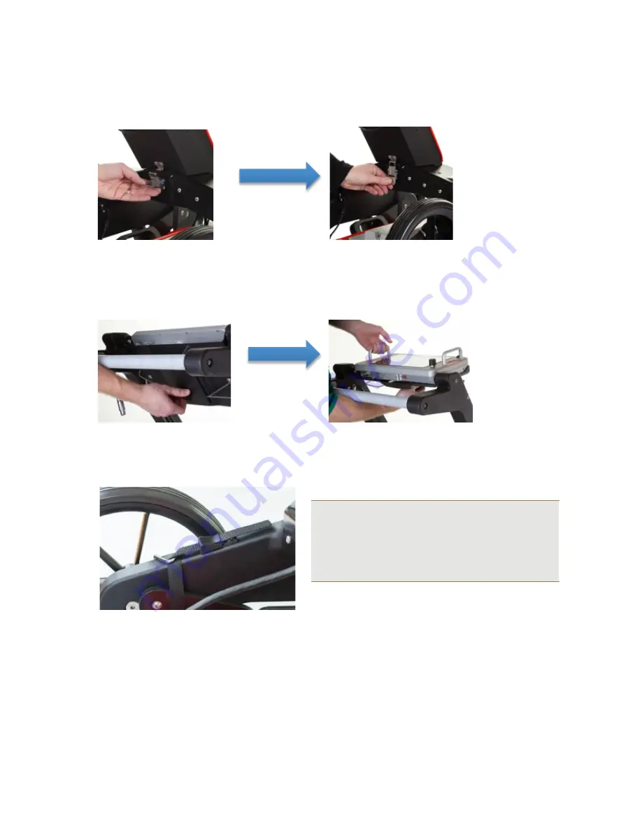
Note: 

Under normal conditions, the antenna should be 

kept in contact with the ground where possible. Position 
the Easy Locator on the surface to be surveyed and 
then adjust the straps so there is a small amount of 
slack. This will compensate for any undulations along 
the survey line.


Fasten the clasp on the rear of the handle assembly 


Slacken the bolt on the rear of the controller, raise the controller to the desired 

viewing angle and re-tighten the bolt.


Adjust the four straps to raise or lower the antenna to the required height


Summary of Contents for Easy Locator Pro HDR Series

Page 1: ...MAL Easy Locator Pro HDR Series User Manual...

Page 2: ...he most technologically advanced and easy to use GPR products with the capability to meet your needs for efficiency and productivity now and into the future Whether this is your first MAL Geoscience p...

Page 3: ...tended only to assist the reader in the use of the product and every effort has been made to ensure that the information in this manual is accurate MAL Geoscience shall not be liable for any loss or d...

Page 4: ...Options Navigator 19 Main Menu 20 Zoom Function 21 Main Menu Icons 21 Measurement Parameter Menu 23 Acquisition Parameters Menu 25 Wheels Edit and Calibration Menu 26 Wheels Edit Options 27 Display P...

Page 5: ...practices and tips are also presented so that the most efficient and productive use can be achieved Additional Resources GPR Training www malags com Support Training GPR Applications www malags com Re...

Page 6: ...round Penetrating Radar Device This device complies with Industry Canada license exempt RSS standards Operation is subject to the following two conditions 1 This device may not cause interference and...

Page 7: ...r Pro HDR Features The HDR series High Dynamic Range is the latest addition to MALA s versatile product range It is a completely new design based on patented cutting edge technology These new antennas...

Page 8: ...8 Accessories and Optional Extras Additional Battery and battery charger Additional Li ion Battery Pack 12 V 3 5 Hour for the MAL Easy Locator Pro Additional MAL Li ion Battery Charger...

Page 9: ...sales department at www malags com corporate contact Note All packing material should be kept in the event that any damage occurred during shipping File any claim for shipping damage with the carrier...

Page 10: ...materials tend to pack down and permit the instrument to move inside its packing box Please read our shipping instructions before returning instruments to MAL Geoscience These instructions can be fou...

Page 11: ...AL Easy Locator Pro is an integrated system consisting of an Easy Locator controller and HDR antenna linked through a single data power cable Hardware Set Up Convenient hand recesses enable easy lifti...

Page 12: ...embly clamp 2 Pull one side of the handle assembly out of out of its fixed position Once released do the same on the opposite side 3 Using the handlebar raise the handle assembly into the upright posi...

Page 13: ...ust the straps so there is a small amount of slack This will compensate for any undulations along the survey line 4 Fasten the clasp on the rear of the handle assembly 5 Slacken the bolt on the rear o...

Page 14: ...k in the power cable and place it towards the mark on the connection Push lightly If you have it in the correct position it will go in its position smoothly To disconnect pull out holding the metal pa...

Page 15: ...r Controller and change the Acquisition Parameters to the correct wheel 5 Power up Start the Easy Locator Pro by pressing the power button on both the HDR antenna and the Easy Locator Controller To tu...

Page 16: ...act your local MAL representative Battery Maintenance and Charging Easy Locator Pro Battery A 12V 8 7Ah Li ion battery pack is shipped with the MAL Easy Locator Pro HDR Antenna and is the recommended...

Page 17: ...e battery until the release pin slots into place Tip Though recharging up to 80 of the full capacity is typically very fast it is recommended to keep the battery charging until it is fully charged to...

Page 18: ...ighest possible level of productivity and safety while operating the MAL Easy Locator Pro HDR Main Display Window 19 Navigating the Menus and Options Navigator 19 Main Menu 20 Zoom Function 21 Main Me...

Page 19: ...ing the Navigator clockwise or anti clockwise The selected item is then executed by pushing the button The Navigator control fitted to Easy Locator Pro Controller works in a similar way to a computer...

Page 20: ...nder the Main Menu vary depending whether the system is in Stopped mode or Started mode Stopped mode Started mode Tip The Easy Locator Pro Controller is equipped with a Zoom Function for enlarging are...

Page 21: ...ller is not turned off immediately the unit has to be put through a power cycling sequence before it can be restarted This is achieved by pressing the power switch on the Controller and then waiting f...

Page 22: ...can be seen when the button is deactivated the level can be gradually adjusted to create the clearest and most interpretable image possible The Contrast button is used to set the contrast of the GPR...

Page 23: ...the gain Selecting Auto deactivates the Time Gain button on the main screen and the Controller will apply the highest gain level for the signal to noise ratio Set the velocity based on soil type Sett...

Page 24: ...he Wheel type icon can choose a selection of predefined wheels from the drop down list Tip Additional wheels and individual calibration can be added to the list by accessing the Acquisition Parameters...

Page 25: ...gering is selected on the Measurement Parameters Menu Acquisition Parameters Menu Choose Forward or Backward depending on the direction of the scan whilst utilising the Measuring Wheel or Cart Select...

Page 26: ...o the standard list This maybe useful if the encoder is attached to a non standard wheel Select Edit Current Wheel calibrate the wheel see Wheel Edit Options for further details Note First use the Sel...

Page 27: ...fter selecting Distance for Calibration Tip For a higher level of accuracy measure a length over the surface where the GPR is being used A longer distance will average out any surface variations Selec...

Page 28: ...Trace view is ON a small window will appear during measurements showing the actual measured trace The intensity of the screen light can be changed with the backlighter option Tip Reducing the backligh...

Page 29: ...t 2D Project 30 3D Grid Project 32 Creating a 3D Project 32 3D Project Settings Menu 37 Object Mapper Project 39 Creating an Object Mapper Project 39 Object Mapper Measurements with Baseline 41 Object...

Page 30: ...ous markers can be inserted into the radargram by selecting the Markers icon A dropdown box containing the marker options will appear when the Markers icon is selected Surface Marker allows a marker t...

Page 31: ...or and enter the value for the true depth Finally press the Navigator again to accept the value and the Easy Locator Controller will automatically calculate the velocity based on the entered value Hyp...

Page 32: ...r Controller will guide you through all steps involved in the data collection to the final processed 3D view of the investigated area Creating a 3D Project Select 3D Grid Project from the Start Menu T...

Page 33: ...any additional comments Finally select Start the Project Before the project commences a summary screen indicating the chosen settings can be reviewed A plan view of the grid and its size is also shown...

Page 34: ...icate the completed line by changing the screen ready for the next line Move the antenna over to the next grid line and select Next Line Repeat these steps until the X axis is completed Move the anten...

Page 35: ...to obtain the best possible top view Next choose an X or Y cross section with a well defined hyperbola Select the Velocity button Increase or decrease the velocity value until the hyperbola becomes a...

Page 36: ...e Navigator to scroll across the data set Select the Y Section button to view the Y axis data in the side view Select the Depth button and use the Navigator to scroll through the time slices in the to...

Page 37: ...onditions can vary rapidly with location and all depth information must be used with caution Set to manual or automatic gain control Note Manual gain activates the Time Gain button on the main screen...

Page 38: ...bient light levels This setting can be adjusted within the range of 0 100 Tip Reducing the backlight will extend the battery life between charges The Background removal filter button is used to remove...

Page 39: ...per Project is created within the Easy Locator Controller it can be directly opened in the ObjectMapper program a Windows based interpretation software for quick mapping of underground features For fu...

Page 40: ...nd Y coordinates of the start and stop positions of the line If no coordinates are available the baseline is defined as 0 m for X and Y start position and then the length of the line for X or Y stop p...

Page 41: ...ed to connect the current profile to the defined baseline Note The baseline can be created anywhere along the GPR profiles e g at the beginning middle or end and the baseline must cross through all th...

Page 42: ...ler and the Object Mapper project will automatically suggest the distance and the angle to the baseline start after 3 passes of the baseline Tip Moving in the opposite direction after each profile is...

Page 43: ...the Project Next select start profile and the screen will return to the main measurement screen Tip With GPS positioning activated the user can complete one long profile in a zig zag formation around...

Page 44: ...screen When on the Quit Screen rotate the Navigator 3 clicks clockwise then 3 clicks counter clockwise and finally 3 clicks clockwise The Easy Locator Controller will now enter the System Menu Select...

Page 45: ...g the latest software from the MAL website downloads page and installing onto a USB data storage device Copy the file ram10img gz and parameter files eeprom_1 eeprom_2 if they exists to the root of a...

Page 46: ...rformed Select Next Screen to access additional System Menu options Default Start Depth value determines the depth widow at start of a scan The entered value has no effect on the total depth of the ti...

Page 47: ...s will be activated see below 3 USB select this option if a simple GPS antenna is attached to the USB port SBAS DGPS Differential correction service areas COM Port settings for external RTK GPS The Se...

Page 48: ...ends of the data cable between the antenna and the MAL Easy Locator Controller Checkthepulseencoderconnectorontherearofthe antenna Restart MAL Easy Locator Pro HDR Controller and Antenna Turn off the...

Page 49: ...a reference station satellite accuracy around 0 5 2 m The available systems for the Easy Locator Controller are currently EGNOS Europe WAAS USA GAGAN India and MSAS Japan G GPR profile Individual line...

Page 50: ...signal from the base antenna The accuracy is around 1 2 cm Network RTK also available in many locations where the correction factor is received via a GSM mobile S Signature A representation of the re...

Page 51: ...n with coefficients set by the user Trace A trace is a single vertical column of GPR data representing the signal traced by a radar pulse as it travels from the instrument into the subsurface Each tra...

Reviews: