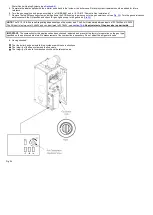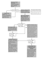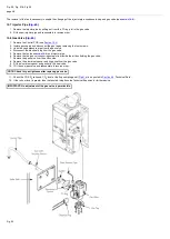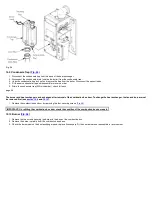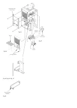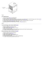
The integrity of the complete flue system and the flue seals.
The integrity of the boiler combustion circuit and relevant seals as described in
The operational gas inlet pressure as described in
and the gas rate as described in
The combustion performance as described in '
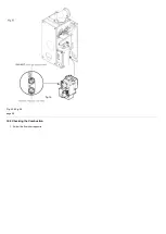
Check the Combustion Performance
3.
Competence to carry out Checking Combustion Performance
B.S. 6798 'Specification for Installation & Maintenance of Gas Fired Boilers not exceeding 70kW' advises that:-
The person carrying out a combustion measurement should have been assessed as competent in the use of a flue gas analyser and the interpretation
of the results.
The flue gas analyser used should be one meeting the requirements of BS7927 or BS-EN50379-3 and be calibrated in accordance with the analyser
manufacturers' requirements.
Competence can be demonstrated by satisfactory completion of the CPA1 ACS assessment, which covers the use of electronic portable combustion
gas analysers in accordance with BS 7967, Parts 1 to 4.
Check the Combustion Performance (CO/CO
2
ratio)
4. Set the boiler to operate at maximum rate as described in
5. Remove the cap from the flue sampling point, insert the analyser probe and obtain the CO/CO
2
ratio.
This must be less than 0.004.
6. If the combustion reading (CO/CO
2
ratio) is greater than this, and the integrity of the complete flue system and combustion circuit seals
has been verified, and the inlet gas pressure and gas rate are satisfactory either:
Perform the 'Annual Servicing - Inspection' (
) & re-check.
Replace the gas valve (
) & re-check.
page 43
14.2 Annual Servicing - Inspection
1. Ensure that the boiler is cool.
2. The boiler cannot be switched off at the boiler, therefore it is important to isolate the electrical supply at the mains fuse.
3. Hazardous materials are not used in the construction of these products, however reasonable care during service is recommended.
4. When replacing the combustion box door after servicing it is essential that the retaining screws are tightened fully.
5. Ensure that both the gas and electrical supplies to the boiler are isolated.
6. Remove the outercase and lower door panel (see Fitting the Outercase,
).
WARNING: The PCB Control and Fan Assembly are 325 Vdc. Isolate at supply before access.
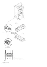
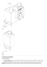
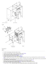
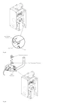
7. Release the four 1/4 turn screws securing the air box door panel and remove the door (
).
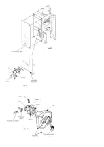
8. Disconnect the leads from the centre and right hand terminals (earth and flame sensing probe) (
). Reconnect in reverse order.
9. Undo the four screws securing the combustion box door and remove the door (
).
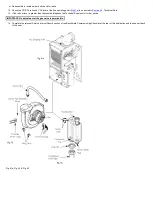
10. Visually check for debris/damage and clean or replace if necessary the following:
a. Burner.
b. Heat exchanger fins.
c. Fan compartment (Check also for condensate leaks).
d. Insulation.
e. Door seals-Important: Pay particular attention to the condition of the combustion box door seals.
f. Electrodes.
g. The condensate trap
NOTE: Remove the trap drain plug and place a vessel underneath to catch the condensate (care should be taken as this could
be hot).
Clean the trap and refit the drain plug. Check for leaks.
h. Top of heat exchanger.
Summary of Contents for Main Heat 12
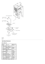
Page 8: ...Fig 3 Fig 4 Fig 5 Fig 6...
Page 38: ...Example 1 Example 2 Example 3...
Page 40: ...Fig E Fig F...
Page 51: ...Fig 31 Fig 32 Fig 33...
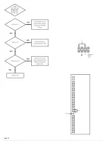
Page 55: ...Fig 35 Fig 36 page 39 12 2 Checking the Combustion 1 Follow the flow chart opposite...
Page 56: ......
Page 63: ...Fig 45 Fig 46...
Page 66: ......
Page 69: ...Fig 55 Fig 56 Fig 57 Fig 58...
Page 72: ...page 52...
Page 74: ...page 54...
Page 75: ...DRY FIRE...
Page 76: ...page 55 IGNITION LOCKOUT...
Page 77: ...page 56 OVERHEAT LOCKOUT...
Page 78: ...page 57 FAN LOCKOUT NOTE The fan is supplied with 325 Vdc...
Page 80: ...warranty This does not affect the customer s statutory rights page 62...
Page 82: ...page 63...

