


page 20
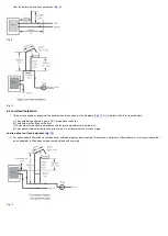
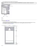
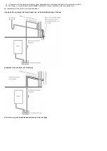
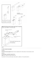
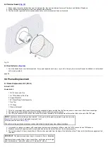
7.7 Flue
NOTE: Due to the high efficiency of the boiler a plume of water vapour will be discharged from the flue.
This should be taken into account when siting the flue terminal.
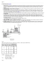
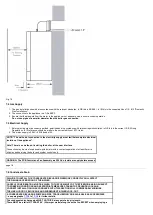
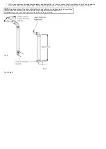
1. The following guidelines indicate the general requirements for siting balanced flue terminals. For GB recommendations are given in BS 5440 Pt.1. For
IE recommendations are given in the current edition of I.S. 813 "Domestic Gas Installations"
.
2. If the terminal discharges onto a pathway or passageway, check that combustion products will not cause a nuisance and that the terminal will not
obstruct the passageway.
3. Take into consideration the effect the plume of vapour may have on neighbours when siting the flue.
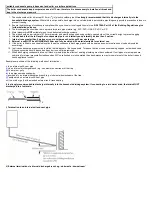
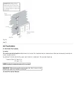
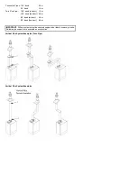
4. Adjacent surfaces close to the flue terminal may need protection from the effects of condensation. Alternatively a flue deflector kit (part no. 248167) is
available.
5. For installation of the flue into an internal corner at the 25mm dimension the flue deflector kit (part no. 248167) must be fitted.
6. * Reduction to the boundary is possible down to 25mm but the Flue Deflector Kit (part no. 248167) must be fitted.
7. If required a suitable terminal guard is available for use with the flue deflector.
8. For fitting under low soffits and eaves the Plume Displacement Kit or Flue Deflector Kit is recommended.
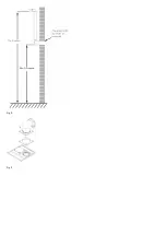
9. If a terminal is less than 2 metres (783/4 in) above a balcony, above ground or above a flat roof to which people have access, then a suitable terminal
guard must be provided.
IMPORTANT
:
Under car ports we recommend the use of the plume displacement kit.
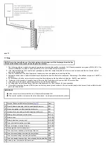
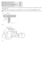
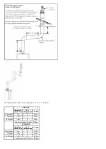
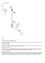
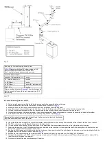
The terminal position must ensure the safe and nuisance - free dispersal of combustion products.
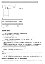
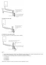
Terminal Position with Minimum Distance (
)
(mm)
A
1
Directly below an opening, air brick, opening windows, etc.
300
B
1
Above an opening, air brick, opening window etc.
300
C
1
Horizontally to an opening, air brick, opening window etc.
300
D
2
Below gutters, soil pipes or drain pipes.
25 (75)
E
2
Below eaves.
25 (200)
F
2
Below balconies or car port roof.
25 (200)
G
2
From a vertical drain pipe or soil pipe.
25 (150)
H
2
From an internal or external corner.
25 (300)
I
Above ground, roof or balcony level.
300
J
From a surface or boundary line facing a terminal.
600
K
From a terminal facing a terminal (Horizontal flue).
1200
From a terminal facing a terminal (Vertical flue).
600
L
From an opening in carport (e.g. door, window) into the dwelling. 1200
M
Vertically from a terminal on the same wall.
1500
Summary of Contents for Main Heat 12
Page 8: ...Fig 3 Fig 4 Fig 5 Fig 6...
Page 38: ...Example 1 Example 2 Example 3...
Page 40: ...Fig E Fig F...
Page 51: ...Fig 31 Fig 32 Fig 33...
Page 55: ...Fig 35 Fig 36 page 39 12 2 Checking the Combustion 1 Follow the flow chart opposite...
Page 56: ......
Page 63: ...Fig 45 Fig 46...
Page 66: ......
Page 69: ...Fig 55 Fig 56 Fig 57 Fig 58...
Page 72: ...page 52...
Page 74: ...page 54...
Page 75: ...DRY FIRE...
Page 76: ...page 55 IGNITION LOCKOUT...
Page 77: ...page 56 OVERHEAT LOCKOUT...
Page 78: ...page 57 FAN LOCKOUT NOTE The fan is supplied with 325 Vdc...
Page 80: ...warranty This does not affect the customer s statutory rights page 62...
Page 82: ...page 63...


