


page 15
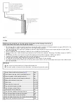
6.7 Sealed Systems (
1.
SAFETY VALVE
- A safety valve complying with the requirements of BS 6750 Part 1 must be fitted close to the boiler on the flow pipe by means of a
horizontal or vertically upward connection with no intervening valve or restrictions and should be positioned to facilitate testing. The valve should be
pre-set and non-adjustable to operate at a pressure of 3 bar. It must be arranged to discharge any water or steam through a pipe to a safe outlet
position.
2.
PRESSURE GAUGE
- A pressure gauge of minimum range 0-4 bar with a fill pressure indicator must be fitted to the system, preferably at the same
point as the expansion vessel in an easily visible position.
3.
EXPANSION VESSEL
- An expansion vessel complying with the requirements of BS 4814 must be fitted to the system by means of a connection
close to the inlet side of the circulating pump in accordance with the manufacturers instructions, the connecting pipe being unrestricted and not less
than 15mm (
1
/
2
in) nominal size. The volume of the vessel should be suitable for the system water content and the nitrogen or air charge pressure
should not be less than the system static head (See
).
Further details of sealed system design can be obtained from BS 5449 and the British Gas publication entitled 'Specifications for Domestic Wet Central
Heating Systems'.
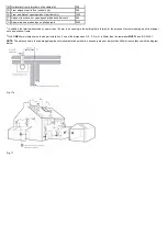
4.
FILLING POINT
- A filling point connection on the central heating return pipework must be provided to facilitate initial filling and pressurising and also
any subsequent water loss replacement / refilling. The sealed primary circuits may be filled or replenished by means of a temporary connection
between the primary circuit and a supply pipe provided a 'Listed' double check valve or some other no less effective backflow prevention device is
permanently connected at the inlet to the circuit and the temporary connection is removed after use. The filling method adopted must be in accordance
with all relevant water supply regulations and use approved equipment.
Your attention is drawn to,
for GB: Guidance G24.2 and recommendation R24.2 of the Water Regulations Guide.
for IE: the current edition of I.S. 813 "Domestic Gas Installations"
.
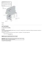
5.
MAKE UP SYSTEM
- A method of replacing water lost from the system should be provided either by means of a make up vessel of not more than 3
litres capacity, mounted above the highest point of the system, or by re-pressurisation of the system.
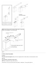
6.
VENTING
- A method of venting the system during filling and commissioning must be provided by fitting automatic air vents or by venting manually.
7.
HOT WATER STORAGE
- The hot water storage vessel must be of the indirect coil type. All components used in the system must be suitable for
operation at 110°C and at the pressure allowed by the safety valve.
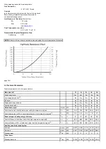
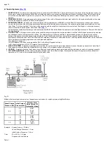
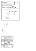
Fig. 13
Method of determining minimum valve of expansion vessel volume for sealed systems using Main Boilers
Vessel Charge
Pressure (Bar)
Initial System
Pressure (Bar)
Multiply Total
Water Content Of
System By (Litres)
0.5
0.5
1.0
1.5
2.0
0.067
0.112
0.207
0.441
1.0
1.0
1.5
2.0
0.087
0.152
0.330
1.5
1.5
2.0
0.125
0.265
Example :- System Volume = 75 litres
Vessel Charge Pressure = 1.0 bar
Initial System Pressure = 1.5 bar
Then
:- 75 x 0.152 = 11.4 litres
Expansion Vessel Volume
Table. 1
Summary of Contents for Main Heat 12
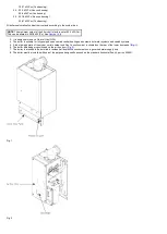
Page 8: ...Fig 3 Fig 4 Fig 5 Fig 6...
Page 38: ...Example 1 Example 2 Example 3...
Page 40: ...Fig E Fig F...
Page 51: ...Fig 31 Fig 32 Fig 33...
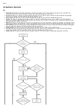
Page 55: ...Fig 35 Fig 36 page 39 12 2 Checking the Combustion 1 Follow the flow chart opposite...
Page 56: ......
Page 63: ...Fig 45 Fig 46...
Page 66: ......
Page 69: ...Fig 55 Fig 56 Fig 57 Fig 58...
Page 72: ...page 52...
Page 74: ...page 54...
Page 75: ...DRY FIRE...
Page 76: ...page 55 IGNITION LOCKOUT...
Page 77: ...page 56 OVERHEAT LOCKOUT...
Page 78: ...page 57 FAN LOCKOUT NOTE The fan is supplied with 325 Vdc...
Page 80: ...warranty This does not affect the customer s statutory rights page 62...
Page 82: ...page 63...