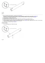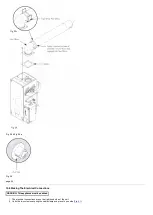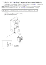
3. The Main 30 Heat is factory set to give a maximum output of 22.0 kW. The Control PCB jumper positions are as follows:
CN11 (Blue) CN12 (Red)
If the installation requires a greater output to achieve the desired room temperature, this can be increased to 30.18 kW and the boiler can be adjusted as
follows (
a) Remove the top right hand securing screw and hinge down the PCB housing.
b) Remove the Red jumper labelled CN12 from the bottom left hand side of the PCB.
c) Hinge back up the PCB housing and secure with screw.
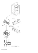
4. Route the incoming electrical cable/s through the grommet in the support bracket. This will prevent damage to the cable.
5. Lay the cable through the cable clamp to gauge the length of cable required when it is connected to the 4-way terminal block.
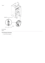
6. Connect the (S/L), (N) and
wires to the 4-way terminal block (
) and refit the cable clamp (
7. Check the electrical installation for; earth continuity, short circuits, resistance to earth, correct polarity and fuse failure.
Summary of Contents for Main Heat 12
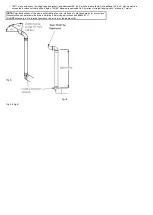
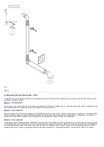
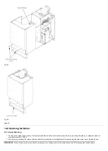
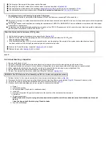
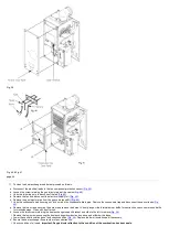
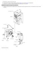
Page 8: ...Fig 3 Fig 4 Fig 5 Fig 6...
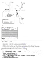
Page 38: ...Example 1 Example 2 Example 3...
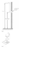
Page 40: ...Fig E Fig F...
Page 51: ...Fig 31 Fig 32 Fig 33...
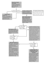
Page 55: ...Fig 35 Fig 36 page 39 12 2 Checking the Combustion 1 Follow the flow chart opposite...
Page 56: ......
Page 63: ...Fig 45 Fig 46...
Page 66: ......
Page 69: ...Fig 55 Fig 56 Fig 57 Fig 58...
Page 72: ...page 52...
Page 74: ...page 54...
Page 75: ...DRY FIRE...
Page 76: ...page 55 IGNITION LOCKOUT...
Page 77: ...page 56 OVERHEAT LOCKOUT...
Page 78: ...page 57 FAN LOCKOUT NOTE The fan is supplied with 325 Vdc...
Page 80: ...warranty This does not affect the customer s statutory rights page 62...
Page 82: ...page 63...

