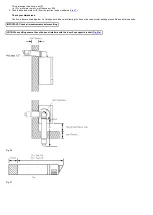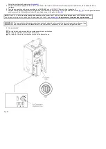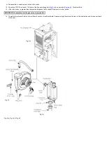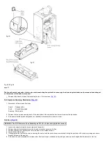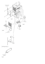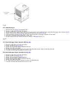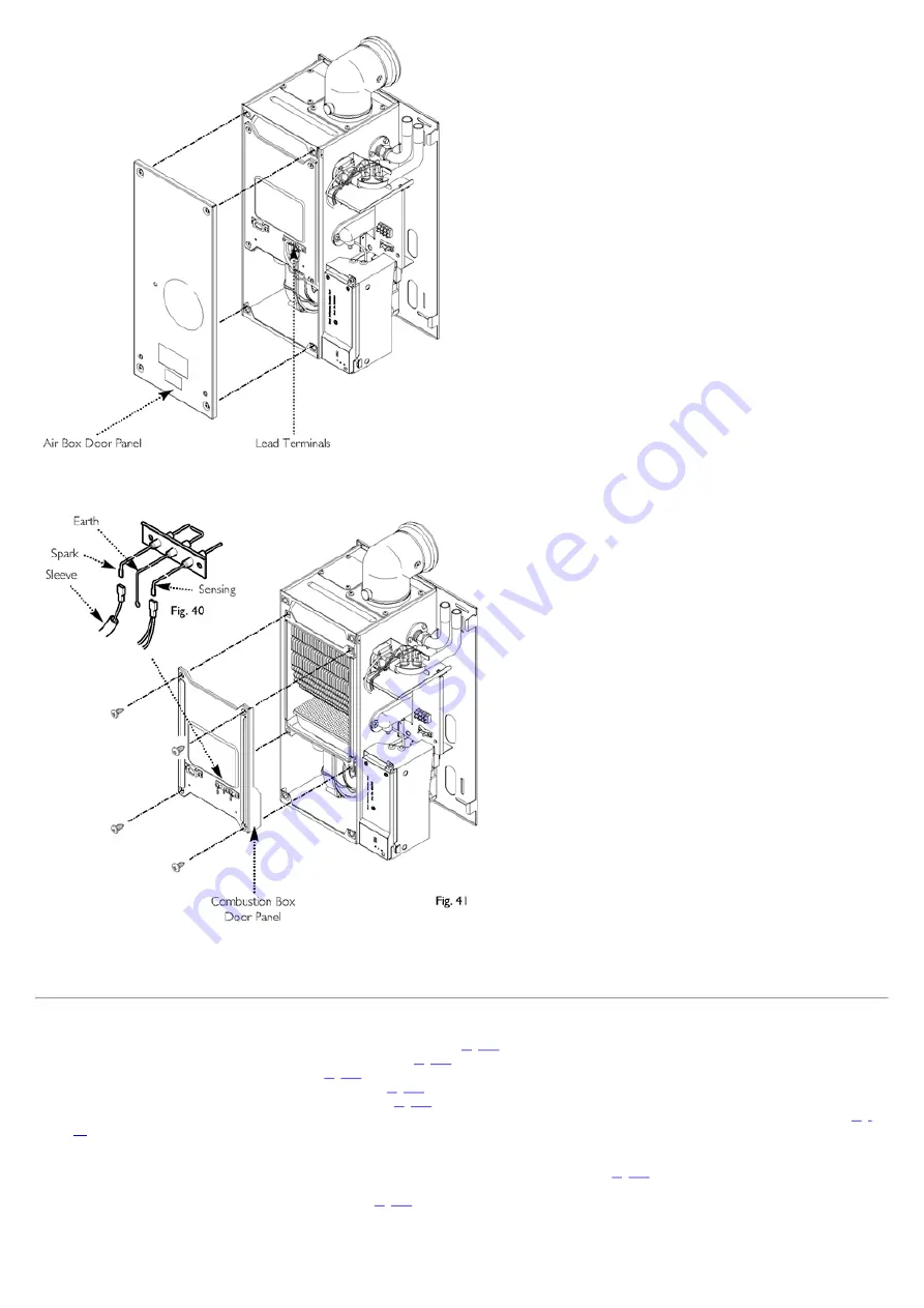
Fig. 39
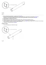
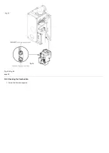
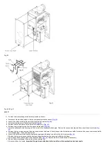
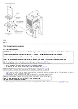
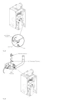
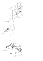
Fig. 40 & Fig. 41
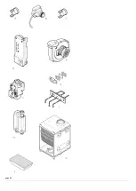
page 44
11. To clean the heat exchanger and burner proceed as follows:
a. Disconnect the electrical leads to the fan component protection sensor (
).
b. Loosen the screw retaining the gas injector pipe at the venturi (
).
c. Undo the two wing nuts to disconnect the fan (
).
d. Remove the fan and disconnect the electrical supply to it (
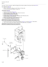
e. Remove the gas injector pipe from the gas valve (push-fit) (
).
g. Remove the two screws securing the burner and remove the burner. Visually inspect the internal burner baffle for obstruction, check seal around baffle
for cracks/damage. Clean with a soft brush.
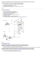
h. Loosen the two screws retaining the heat exchanger support bracket and slide to the left to remove(
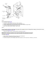
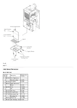
i. Remove the four screws securing the heat exchanger/combustion box base and withdraw the base.
j. Lower the central insulation panel and check condition (
). Replace the lower insulation pad if necessary.
k. Ensure the heat exchanger fins are clear of any obstruction.
l. Check condition of all seals.
Important: Pay particular attention to the condition of the combustion box door seals.
Summary of Contents for Main Heat 12
Page 8: ...Fig 3 Fig 4 Fig 5 Fig 6...
Page 38: ...Example 1 Example 2 Example 3...
Page 40: ...Fig E Fig F...
Page 51: ...Fig 31 Fig 32 Fig 33...
Page 55: ...Fig 35 Fig 36 page 39 12 2 Checking the Combustion 1 Follow the flow chart opposite...
Page 56: ......
Page 63: ...Fig 45 Fig 46...
Page 66: ......
Page 69: ...Fig 55 Fig 56 Fig 57 Fig 58...
Page 72: ...page 52...
Page 74: ...page 54...
Page 75: ...DRY FIRE...
Page 76: ...page 55 IGNITION LOCKOUT...
Page 77: ...page 56 OVERHEAT LOCKOUT...
Page 78: ...page 57 FAN LOCKOUT NOTE The fan is supplied with 325 Vdc...
Page 80: ...warranty This does not affect the customer s statutory rights page 62...
Page 82: ...page 63...


