Maeda CC1908S-1 Operation Manual Download Page 79

M A E D A

 Crawler Crane


4.2  MONITOR


5/2020 CC1908S-1 

4-13 

[13] Searcher Hook Setting 

 WARNING 

With or without searcher hook setting must be 
matched to the actual condition. The wrong 
settings can cause a serious accident. 

By touching these buttons With/Without Searcher 
Hook and Winch ON/OFF can be switched. 


[ With/Without Searcher Hook ]  

Touch to switch between With or Without 
Searcher Hook.  

•  With Searcher Hook:  

Select this when searcher hook is mounted.  
This switches to searcher hook mode.  

•  Without Searcher Hook:  

Select this when searcher hook is not 
mounted.  


Switch this when mounting or removing the 
searcher hook. When the setting is changed, 
the moment limiter display will change and 
the rated total load will change.  

[ Winch ON/OFF ]


Touch to switch the Winch ON or OFF.  

• OFF


:Winch does not work even when winch is 

operated.   

• ON 

The winch works as usual.  


This is not available when the main hook is 
used or without the searcher hook attached.  


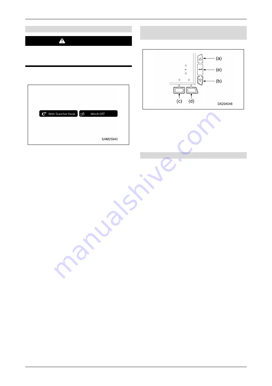
[14] Pop-up selector switches  
 

(User Settings screen) 

Press to operate the pop-up functions. 


(a) Up  
(b) Down  
(c) Left  
(d)  Right   
(e) Select/enter 
 

[15] Home switch 

Press to return to the previous screen. 
Press and hold to return to the home screen. 


Summary of Contents for CC1908S-1

Page 1: ...s must read this manual before operating this machine This manual should be kept near the machine for reference and periodically reviewed by all personnel who will come into contact with it NOTICE MAE...

Page 2: ......

Page 3: ...er 2 SAFETY 2 1 BASIC PRECAUTIONS 2 2 2 2 SAFETY LABEL LOCATIONS 2 8 Chapter 3 SPECIFICATIONS MAIN SPECIFICATIONS 3 2 DIMENSIONAL DRAWINGS 3 4 RATED TOTAL LOAD CHARTS 3 8 3 3 4 1 RATED TOTAL LOAD CHAR...

Page 4: ...VICE 4 20 MOMENT LIMITER MECHANISM 4 21 MOMENT LIMITER ABNORMALITY MESSAGE DISPLAY 4 22 PROHIBITED OPERATIONS AFTER OVERLOAD 4 22 RECOVERY OPERATION AFTER OVERLOAD 4 22 MOMENT LIMITER DISPLAY 4 26 EXP...

Page 5: ...5 12 5 3 1 4 PRECAUTIONS WHEN TRAVELLING ON SLOPES 5 12 5 3 1 5 PRECAUTIONS WHEN STARTING AND OPERATING 5 13 5 3 2 1 MOVING BEFORE AND AFTER WORK DURING TRANSPORTATION 5 15 5 3 2 2 MOVING DURING WORK...

Page 6: ...K BLOCK SIMPLE STOWAGE 5 40 5 4 11 2 NORMAL HOOK BLOCK STOWAGE 5 42 PICK CARRY OPERATION 5 44 AIR CONDITIONER OPERATION 5 47 5 6 3 1 AUTO MODE 5 50 5 6 3 2 MANUAL OPERATION 5 50 5 6 3 3 OPERATION STOP...

Page 7: ...CE AND INSPECTION MAINTENANCE PRECAUTIONS 6 2 BASIC MAINTENANCE 6 4 LEGAL INSPECTION 6 7 PARTS REPLACEMEMT 6 7 USE OF FUEL AND LUBRICATING OIL 6 10 STANDARD TIGHTENING TORQUES 6 13 FUSES 6 16 FUSIBLE...

Page 8: ...6 75 WINCH WIRE ROPE REEVING SYSTEM AND RATED TOTAL LOAD 6 77 CORRECTING WINCH WIRE ROPE TWISTING 6 78 WINCH WIRE ROPE REPLACEMENT 6 79 BOOM TELESCOPING WIRE ROPE INSPECTION ADJUSTMENT 6 82 DERRICK WI...

Page 9: ...IR BLEEDING 6 97 WINCH MOTOR AIR BLEEDING 6 97 TRAVEL MOTOR AIR BLEEDNIG 6 98 DPF REGENERATION 6 99 DPF STATIONARY REGENERATION 6 100 BEFORE STORING MACHINE 6 101 DURING STORAGE 6 102 AFTER STORAGE 6...

Page 10: ...CONTENTS M A E D A Crawler Crane viii 5 2020 CC1908S 1 This Page Intentionally Left Blank...

Page 11: ...INTRODUCTION...

Page 12: ...achine before carefully reading this manual Always keep this manual at hand so you can refer to it when necessary If this manual becomes lost or damaged contact us or our sales service agency promptly...

Page 13: ...to avoid such hazards This manual also uses the following indications for precautions that must be adhered to and for other useful information IMPORTANT This denotes that failure to properly handle th...

Page 14: ...operators may be involved in occupational accidents Be sure to adhere to the safety precautions described in this manual when operating this machine QUALIFICATIONS REQUIRED FOR CRANE OPERATION Only pe...

Page 15: ...own power in the worksite and lifting objects weighing up to the rated total load MACHINE CONFIGURATION 1 Upper slewing body 2 Carrier 3 Safety device In this manual the front rear left and right dire...

Page 16: ...ination alarm Working status lamp Level gauge Safety lock lever and Working radius limiter MACHINE FUNCTIONS 1 Upper slewing body The upper slewing body can rotate through 360 degrees using the slewin...

Page 17: ...ht of the hoisting accessories hooks and slinging ropes from the rated total load 3 Working radius The horizontal distance between the slewing axis and the hook centreline 4 Boom length Refers to the...

Page 18: ...both the engine and crane Pay particular attention to the following during the running in period Be sure to allow the engine and hydraulic equipment to warm up after starting the engine Refer to 5 2 4...

Page 19: ...Chapter 2 SAFETY...

Page 20: ...k supervisor and ensure that safety takes priority while working Adhere to crane operation basics while working Be sure to carry out pre work inspections before operating the machine Do not work under...

Page 21: ...icate the details of the problem the name and contact information of the storage manager and the length of time in storage Make sure the machine cannot be moved e g by placing chocks in the crawler tr...

Page 22: ...phone while driving or operating the machine This may cause incorrect operation resulting in serious personal injury PROVISION OF FIRE EXTINGUISHER AND FIRST AID BOX Always observe the following point...

Page 23: ...may occur due to short circuiting of electrical systems The following points must be strictly observed Keep all electrical wiring connections clean and make sure they are securely in place Inspect el...

Page 24: ...crane and set the lock lever 1 to the LOCK position L and turn off the engine Inadvertently touching control levers may cause the machine to suddenly move resulting in serious personal injury When le...

Page 25: ...d Some combinations of attachments and optional units may interfere with the cab and machine parts possibly causing serious personal injury Check that attachments and optional units used do not interf...

Page 26: ...ay be used to explain the meaning of the different signal words as defined in this standard DANGER indicates a hazardous situation that if not avoided will result in death or serious injury WARNING in...

Page 27: ...M A E D A Crawler Crane 2 2 SAFETY LABEL LOCATIONS 5 2020 CC1908S 1 2 9 SAFETY LABEL LOCATIONS IN THE CAB...

Page 28: ...2 2 SAFETY LABEL LOCATIONS M A E D A Crawler Crane 2 10 5 2020 CC1908S 1 SAFETY LABEL LOCATIONS OUTSIDE THE CAB 1 2...

Page 29: ...M A E D A Crawler Crane 2 2 SAFETY LABEL LOCATIONS 5 2020 CC1908S 1 2 11 SAFETY LABEL LOCATIONS OUTSIDE THE CAB 2 2...

Page 30: ...2 2 SAFETY LABEL LOCATIONS M A E D A Crawler Crane 2 12 5 2020 CC1908S 1 FLY JIB SAFETY LABEL LOCATIONS...

Page 31: ...M A E D A Crawler Crane 2 2 SAFETY LABEL LOCATIONS 5 2020 CC1908S 1 2 13 SEARCHER HOOK LABEL LOCATIONS...

Page 32: ...2 2 SAFETY LABEL LOCATIONS M A E D A Crawler Crane 2 14 5 2020 CC1908S 1 1 520 3641500 Safety operation 2 520 2263200 Working range Rated total load chart...

Page 33: ...A Crawler Crane 2 2 SAFETY LABEL LOCATIONS 5 2020 CC1908S 1 2 15 3 556 4596300 Caution for Wash 5 520 3619200 Number of falls Select 4 520 3618900 Control lever pattern 6 520 2268600 Moment limiter op...

Page 34: ...2 2 SAFETY LABEL LOCATIONS M A E D A Crawler Crane 2 16 5 2020 CC1908S 1 7 520 3641400 Safety instructions 8 556 4596200 Do not operate 9 520 3639100 Emergency operation pattern...

Page 35: ...CC1908S 1 2 17 10 349 4427800 High temperature 11 585 4738600 Fuel 12 556 4597000 High temperature 13 556 3460700 Crush hazard 14 556 4597100 Get caught 15 103 4589800 High pressure 16 556 4596600 El...

Page 36: ...rane 2 18 5 2020 CC1908S 1 18 CL000210000 Fall Don t ride 19 103 4590200 Get caught in winch 20 103 4592400 Get caught in hook 21 556 4596800 Crush hazard 22 520 4843000 Machine weight 24 CL000240110...

Page 37: ...EL LOCATIONS 5 2020 CC1908S 1 2 19 25 520 4843300 Connecting position Don t lifting 26 CL000220030 Accumulator 27 584 4581700 Don t ride 28 585 4739000 Disconnect switch 29 103 4576900 Boom lifting 30...

Page 38: ...er Crane 2 20 5 2020 CC1908S 1 31 584 3438000 Wire rope CE plate 32 106 3399300 Hook CE plate 33 585 4739200 Override switch 34 S520A3929170 EPA regulation B1 542 4781300 Blade operation pattern Optio...

Page 39: ...M A E D A Crawler Crane 2 2 SAFETY LABEL LOCATIONS 5 2020 CC1908S 1 2 21 F1 520 2263400 Working range Rated total load chart for Fly jib Option F2 520 2272400 Fly jib installation Option...

Page 40: ...A E D A Crawler Crane 2 22 5 2020 CC1908S 1 F3 520 2272500 Fly jib stowage Option F4 556 4580700 Don t lifting Option F5 CL000100001 Pin hole Option F6 CL000120011 sandwich the hand Option F7 585 471...

Page 41: ...wler Crane 2 2 SAFETY LABEL LOCATIONS 5 2020 CC1908S 1 2 23 F8 106 4719500 Max capacity Option F9 CL000010000 Refer to the manual Option F10 106 4719600 Hook CE plate Option F11 520 4845900 Fly jib fa...

Page 42: ...LABEL LOCATIONS M A E D A Crawler Crane 2 24 5 2020 CC1908S 1 S1 520 2276200 Working range Rated total load chart for Searcher hook Option S2 520 4856300 Max capacity Option S3 520 4856400 Crush haza...

Page 43: ...CATIONS 5 2020 CC1908S 1 2 25 S4 520 4856500 Hook CE plate Option S5 585 3558400 Serial plate Option S6 103 4589600 Pin hole Option S7 520 4857100 sandwich the hand Option S8 520 4857000 Searcher hook...

Page 44: ...2 2 SAFETY LABEL LOCATIONS M A E D A Crawler Crane 2 26 5 2020 CC1908S 1 This Page Intentionally Left Blank...

Page 45: ...SPECIFICATIONS...

Page 46: ...12 46 m to 15 93 m to 19 40 m Telescoping stroke Extending time 13 88 m 51 sec Derricking system Type Double acting hydraulic cylinder direct thrust system with hydraulic automatic locking device Der...

Page 47: ...Blade Weight and dimensions Main body weight 950 kg Overall length width height 7 380 mm 2 490 mm 3 015 mm Equipment Item Searcher hook Weight and dimensions Main body weight 70 kg Overall length widt...

Page 48: ...3 2 DIMENSIONAL DRAWINGS M A E D A Crawler Crane 3 4 5 2020 CC1908S 1 DIMENSIONAL DRAWINGS...

Page 49: ...M A E D A Crawler Crane 3 2 DIMENSIONAL DRAWINGS 5 2020 CC1908S 1 3 5...

Page 50: ...3 2 DIMENSIONAL DRAWINGS M A E D A Crawler Crane 3 6 5 2020 CC1908S 1...

Page 51: ...M A E D A Crawler Crane 3 2 DIMENSIONAL DRAWINGS 5 2020 CC1908S 1 3 7...

Page 52: ...with boom sections 3 4 or 5 extended If the boom length exceeds the stipulated length operations should be carried out using the rated total load for the next boom length up The rated total load char...

Page 53: ...m 4 and 19 40 m boom 5 columns at the top denote the respective states of the following figures 1 5 52 m boom 1 All the booms are retracted 2 8 99 m boom 2 Booms 3 4 and 5 are retracted while boom 2 a...

Page 54: ...e extended to an intermediate length mark is exposed half way from boom 3 If booms 4 and 5 are extended even by a small extent work within the capacity indicated in this column 5 19 40 m boom 5 All th...

Page 55: ...3 340 2 390 6 000 3 170 1 590 3 130 3 040 2 390 6 430 2 850 1 430 2 840 2 810 N A 2 390 6 500 2 800 1 400 2 790 2 770 2 350 7 000 2 490 1 250 2 500 2 540 2 140 8 000 1 960 980 2 030 2 140 1 800 N A 8...

Page 56: ...3 340 2 390 6 000 3 170 1 590 3 130 3 040 2 390 6 430 2 850 1 430 2 840 2 810 N A 2 390 6 500 2 800 1 400 2 790 2 770 2 350 7 000 2 490 1 250 2 500 2 540 2 140 8 000 1 960 980 2 030 2 140 1 800 8 820...

Page 57: ...3 090 2 390 6 000 3 090 1 500 3 090 3 040 2 390 6 430 2 850 1 430 2 840 2 810 N A 2 390 6 500 2 800 1 400 2 790 2 770 2 350 7 000 2 490 1 250 2 500 2 540 2 140 8 000 1 960 980 2 030 2 140 1 800 8 820...

Page 58: ...520 750 1 520 1 520 1 520 6 430 1 520 750 1 520 1 520 N A 1 520 6 500 1 520 750 1 520 1 520 1 520 7 000 1 520 750 1 520 1 520 1 520 8 000 1 520 750 1 520 1 520 1 520 8 820 1 520 750 1 520 1 520 1 520...

Page 59: ...720 670 620 1020 820 620 520 420 370 320 70 1120 820 770 720 670 620 520 820 620 520 420 370 320 270 60 820 770 720 670 620 520 620 520 420 370 320 270 50 770 720 670 620 520 520 420 370 320 270 40 5...

Page 60: ...include dynamic effects of swing extending retracing lowering raising wind or adverse conditions Crane users must reduce Rated Total Loads ratings to take all conditions into account 3 The load radius...

Page 61: ...520 2000 1520 2000 1520 1600 1520 6 85 2000 2000 1520 2000 1520 1930 1520 1600 1520 7 00 2000 1520 1950 1520 1890 1520 1600 1520 7 14 2000 1520 1900 1520 1840 1520 1600 1520 7 28 1950 1520 1850 1520 1...

Page 62: ...t A in the figure indicates the boom angle and point B the lifting height above the ground The working radius for points A and B are the same However they differ when using a single fall 2 The working...

Page 63: ...M A E D A Crawler Crane 3 4 WORKING RADIUS LIFTING HEIGHT DIAGRAMS 5 2020 CC1908S 1 3 19...

Page 64: ...3 4 WORKING RADIUS LIFTING HEIGHT DIAGRAMS M A E D A Crawler Crane 3 20 5 2020 CC1908S 1...

Page 65: ...M A E D A Crawler Crane 3 4 WORKING RADIUS LIFTING HEIGHT DIAGRAMS 5 2020 CC1908S 1 3 21...

Page 66: ...3 4 WORKING RADIUS LIFTING HEIGHT DIAGRAMS M A E D A Crawler Crane 3 22 5 2020 CC1908S 1 This Page Intentionally Left Blank...

Page 67: ...PARTS AND CONTROLS...

Page 68: ...Boom 2 Boom working light 3 Boom derricking cylinder 4 Winch 5 Head light 6 Wiper Front window 7 Wiper Roof window 8 Sprocket travel motor 9 Track frame 10 Idler 11 Crawler 12 Hook block 13 Overwindin...

Page 69: ...y lock lever 4 Left hand control lever 5 Travel levers 6 Accelerator pedal 7 Monitor 8 Right hand control lever 9 USB power supply port 10 Accessory power supply 11 Sun visor 12 Sun shade 13 Interior...

Page 70: ...switches to the home screen once loading is complete When the engine is started the battery voltage may suddenly decrease depending on the temperature and battery condition If this occurs the monitor...

Page 71: ...tting switch 7 DPF stationary regeneration switch 8 Camera selector switch 9 Travel 1st speed 2nd speed selector switch 10 Home switch 11 Travel status 12 Level gauge 13 Winch 1st speed 2nd speed disp...

Page 72: ...tationary regeneration For details on the DPF regeneration request lamp and DPF stationary regeneration refer to 6 19 7 DPF DIESEL PARTICULATE FILTER REGENERATION on P 6 99 IMPORTANT The machine canno...

Page 73: ...jib is extended Travel status display The display changes according to the travel mode selection and machine status Stationary mode Travel mode Travel prohibited Travel is prohibited in the following...

Page 74: ...and control lever toggles the display between 1 and 2 The speed will be limited to 1st speed if the hoisted load is 0 5 t or greater 14 Moment limiter display Refer to 4 3 4 1 MOMENT LIMITER DISPLAY o...

Page 75: ...re version 6 Hook grounding stop on off selection 7 Fly jib installation stowage Only with fly jib mounted 8 Monitor brightness adjustment 9 Time setting 10 Consumables display 11 Switch operation ton...

Page 76: ...r on the hook part of the moment limiter changes and the rated total load also changes The setting will be fixed at Single Fall Fixed when the fly jib is mounted and this cannot be changed even when t...

Page 77: ...l keypad displayed then press 2 24 hour 12 hour clock selection Tap to change between a 24 hour clock and a 12 hour clock 3 Summer time ON OFF Tap to turn on off the summer time setting ON Time displa...

Page 78: ...e screen after startup None The consumables icon is not displayed at all 11 Switch operation tone on off selection Tap to enable or disable the switch operation sound OFF The operation sound is disabl...

Page 79: ...mode Without Searcher Hook Select this when searcher hook is not mounted Switch this when mounting or removing the searcher hook When the setting is changed the moment limiter display will change and...

Page 80: ...ay and the standard display WARNING The camera images should only be used as a guide Be sure to check the machine surroundings visually The camera must be readjusted if it has been moved during replac...

Page 81: ...ck the full 360 degrees around the machine Displays a bird s eye view of the machine on the left side of the screen and the rear view on the right side of the screen allowing you to check the surround...

Page 82: ...2 Fly jib length display 3 Fly jib angle display 4 Main boom fly jib operation selector switch This section describes only those items that differ in fly jib mode For details on other items refer to 4...

Page 83: ...lel to the main boom As the fly jib is lowered the angle increases The angle of the fly jib indicates the angle with respect to the main boom so it is not affected by raising or lowering the main boom...

Page 84: ...8 5 2020 CC1908S 1 4 2 6 SEARCHER HOOK MODE SCREEN 1 Searcher hook position display 2 Searcher hook position switch Only the items that change when in Searcher Hook mode are explained For other items...

Page 85: ...towed and changed to crane operation with the main hook In this condition the weight of the searcher hook will be added to the actual load 2 Searcher Hook Position Switch Use this to switch the search...

Page 86: ...re sensor derricking cylinder 2 units 4 Over un winding prevention device winch 5 Overwinding detector side of boom tip 6 Working status lamp A Rotating red lamp warning lamp when load factor is 100 o...

Page 87: ...e starting crane operations be sure to inspect the moment limiter to make sure that it operates correctly MOMENT LIMITER MECHANISM The moment limiter knows the current posture based on the boom angle...

Page 88: ...e crane may actually create dangerous situations Take care when operating the crane to avoid overload PROHIBITED OPERATIONS AFTER OVERLOAD DANGER The following crane operations are prohibited after th...

Page 89: ...working status lamp changes from green to yellow and the alarm sounds to notify the operator and persons in the surrounding area that the hoisted load is approaching the rated total load 3 When load f...

Page 90: ...over after an overload has occurred use one of the following operations to reverse the crane from the position where overload occurred The crane must be first moved back to within the safety area with...

Page 91: ...urn the boom hoisting lever to the neutral position DANGER Only use this switch when overload has occurred through entry into the overload region while lowering or extending the boom Do not use under...

Page 92: ...display 3 Actual working radius display 4 Rated working radius display 5 Hook ground contact indicator 6 Boom angle display 7 Boom length display 8 Boom height display 9 Load factor display 10 Over u...

Page 93: ...Rated total load display This displays the rated total load i e the total weight of the hook hoisting accessories and hoisted load that the crane can currently hoist This is calculated according to co...

Page 94: ...e from the ground to the boom tip 9 Load factor display The moment limiter load factor status is indicated by illuminated bars as the load factor varies Load factor display 100 to 110 Load factor 100...

Page 95: ...3 3 2 RECOVERY OPERATION AFTER OVERLOAD on P 4 22 OVERWINDING PREVENTION DEVICE IMPORTANT When hoisting the hook be careful of the clearance between the hook and boom Extending the boom raises the hoo...

Page 96: ...M LOWER LIMIT DETECTION When the boom length is 6 0 m or greater boom lowering stops automatically to prevent the boom from falling below a horizontal position MOMENT LIMITER FUNCTION WHEN USING FLY J...

Page 97: ...he following state of operation The value of the rated total load displayed on the monitor is switched to the value for the searcher hook The number of falls is fixed to the Searcher Hook or Single Fa...

Page 98: ...h this switch turned on after the moment limiter has detected that the rated total load was exceeded during crane operation and automatically stops the operation This may cause boom damage or machine...

Page 99: ...is extended and consequently the hook block 1 nears the boom 4 tip and pushes up the weight 3 the overwinding prevention device automatically stops the hook block 1 from hoisting and the boom 4 from e...

Page 100: ...wire rope remaining on the winch drum falls below a certain level during lowering operations A buzzer sounds intermittently to alert the operator of over un winding if the operator attempts to lower t...

Page 101: ...selector switch 4 Hook stowage lever 5 Starter switch 6 Light switch 7 Front window wiper switch 8 Roof window wiper switch 9 Buzzer cancelling switch 10 Winch 1st speed 2nd speed selector switch 11...

Page 102: ...operation This is available only when the fly jib is mounted Selection is not possible unless the control levers are in the neutral position Check the monitor display before operating 4 Hook stowage l...

Page 103: ...W lamp illuminates when the starter switch is turned to the ON position When the lamp illuminates wait until the lamp goes out before turning the switch to the START position to start the engine The e...

Page 104: ...hoisted load at high speed may cause serious personal injury due to the machine toppling breakage or dropping the load If the hoisted load weighs 0 5 t or more it cannot be operated at high speed eve...

Page 105: ...o turn off this switch may drain the battery Be sure to turn the switch back to the OFF position after using the interior lamp The interior lamp can be turned on even when the starter switch is in the...

Page 106: ...4 7 ACCESSORIES M A E D A Crawler Crane 4 40 5 2020 CC1908S 1 4 7 ACCESSORIES 1 USB power supply port 2 Accessory power supply 3 Cup holder 4 Sun shade 5 Sun visor 6 Emergency escape hammer...

Page 107: ...nction 2 Accessory power supply IMPORTANT The accessory power supply is 24 V Do not use this to power 12 V equipment It can be used as an accessory socket 100 W 24 V 5 A 3 Cup holder This is located o...

Page 108: ...are not to be injured by pieces of scattered broken glass When escaping remove any pieces of glass from the window frame to avoid injury Also take care not to slip on pieces of the broken glass A hamm...

Page 109: ...erious personal injury When the operator leaves the operator s seat or while operation is suspended check that the safety lock lever is securely in the lock L position When pulling up or pushing down...

Page 110: ...s facing forward or backward Use these levers to move the machine forward backward stop change direction and adjust the travel speed a Forward Push the levers forward b Reverse Pull the levers toward...

Page 111: ...the left N Neutral Release your hand from the lever The hook block and boom angle hold their positions when they are stopped 5 Accelerator pedal WARNING Depress the pedal slowly and operate carefully...

Page 112: ...e front window hold the handle securely with both hands and pull it up Do not release your hands until it is locked in the automatic locking catch Do not operate the front window wiper with the front...

Page 113: ...ow push down the levers B two locations with the thumb and disengage the lock of the upper part of the front window The upper part of the front window can be detached 5 Hold and pull up the right and...

Page 114: ...e the safety lock lever 1 securely in the lock position L 3 While holding the right and left handles A pull the levers B downward to unlock 4 Hold the handles A on the front window with both hands pus...

Page 115: ...efore opening or closing 4 11 RETRACTABLE SEAT BELT HANDLING WARNING Before wearing the seat belt check the belt mounting bracket and installed belt for any abnormalities If they are worn or damaged r...

Page 116: ...4 11 RETRACTABLE SEAT BELT HANDLING M A E D A Crawler Crane 4 50 5 2020 CC1908S 1 This Page Intentionally Left Blank...

Page 117: ...OPERATION...

Page 118: ...tion is nevertheless required when operating the machine as there are some blind spots from the operator s seat There is a risk of serious personal injury when travelling or operating the machine in l...

Page 119: ...ents Persons who have sustained electric shocks by holding sling ropes guide ropes or other conductors when the machine became live should be instructed to evacuate on their own Never attempt to help...

Page 120: ...G ENGINE PAY ATTENTION TO WARNING SIGNS DANGER DO NOT OPERATE warning signs indicate that the machine is being inspected or maintained Do not start the engine or touch the control levers Ignoring warn...

Page 121: ...nd the winch and check that they operate correctly before starting work Before starting the engine ensure that the AUTO GLOW lamp goes off Operating the machine without sufficiently warming up the eng...

Page 122: ...position L 2 Check that each control lever is in the Neutral position Unless they are touched the control levers will be in the Neutral position 3 Insert the key into the starter switch 2 turn the ke...

Page 123: ...charge If the engine fails to start wait for more than 30 seconds before retrying If the fuel has temporarily run out wait for fuel to be fed in by the feed pump before starting 1 Check that the lock...

Page 124: ...ming up the engine alone does not warm up the hydraulic equipment Warm up the hydraulic equipment separately from the engine Warming up the hydraulic equipment warms up the hydraulic oil enabling warm...

Page 125: ...ct with the ground 6 Slowly operate the right hand control lever fully to the Lower side push outside to fully lower the boom Operate the right hand control lever to the Hoist up side pull backward as...

Page 126: ...3 Remove the starter switch key MACHINE TRAVELLING PRECAUTIONS WHEN TRAVELLING WARNING Failure to adhere to these precautions when travelling may result in serious personal injury 5 3 1 1 TRAVELLING...

Page 127: ...orn to warn people in the vicinity When travelling check that the travelling alarm sounds normally When the view to the rear of the machine is obstructed appoint a marshaller and take care to prevent...

Page 128: ...ble of travelling on slopes of up to 20 degrees but it is liable to become unstable on slopes of more than 15 degrees If the buzzer sounds stop travelling any further move to a safe location and take...

Page 129: ...y result in delays in discovering machine abnormalities as well as personal injury or machine damage Inspection should be carried out in a clear area No unauthorized persons should be allowed to appro...

Page 130: ...result in skin freezing to the metal surface Remove snow or ice build up on the machine as this may make the safety nameplates hard to read Snow or ice on the boom in particular should be completely...

Page 131: ...sture shown in the figure when moving to and from the worksite and when moving to and from transportation locations Fully retract the boom Fully lower the boom Stow the hook block in the designated st...

Page 132: ...e machine to move suddenly Be sure to operate the pedal cautiously When travelling check that the travelling alarm operates normally All crane operations are disabled while the crane is travelling Sto...

Page 133: ...ws If the sprocket A is at the rear of the machine pull the travel levers slowly toward you to start moving If the sprocket A is at the front of the machine push the travel levers 5 slowly forward to...

Page 134: ...rd direction Pulling the lever toward you turns the machine to the left in the reverse direction A Left turn in forward direction B Left turn in reverse direction To turn to the right push the left tr...

Page 135: ...serious personal injury Be sure to select a level place and stop the machine there before starting work After stopping the machine check the level using the level gauge The moment limiter calculates...

Page 136: ...rol levers pedals and switches under no load and check that they operate normally Repair immediately if any abnormality exists Check safety devices such as the moment limiter overload prevention devic...

Page 137: ...ating COLD WEATHER PRECAUTIONS Remove snow and defrost the surfaces of the slewing gear boom and around the winch and check that they operate correctly before starting work Check the winch brake to en...

Page 138: ...amage the boom Take care when raising the boom as this increases the probability of toppling backward when the wind blows from the front If an earthquake occurs stop operations and wait for the earthq...

Page 139: ...ng ropes to either end of the load PRECAUTIONS WHEN HANDLING WIRE ROPE Wire ropes wear out over time Be sure to inspect wire ropes each time before work and replace immediately when the wear limit is...

Page 140: ...m the winch lever Winding up of the hook block stops Next operate the winch lever downward i e push it forward to wind down the hook block Boom extending also hoists the hook block Allow sufficient di...

Page 141: ...ck come into contact with the ground by operating the winch lever When lowering the hook block a long distance such as for underground work be sure to leave at least three turns of wire rope on the wi...

Page 142: ...pple due to an offset centre of gravity It can also cause the hoisted load to fall or cause damage to the boom If joint hoisting is required for unavoidable reasons discuss and establish a work scheme...

Page 143: ...rohibited DO NOT OPERATE USING DERRICKING FORCE Drawing in a load or standing it upright by boom derricking is prohibited DO NOT PULL LATERALLY DRAW IN OR HOIST DIAGONALLY Pulling a load laterally dra...

Page 144: ...the machine to topple and is prohibited under normal circumstances If Pick Carry is unavoidable refer to 5 5 PICK CARRY OPERATION on P 5 44 and adhere to the instructions provided DO NOT OPERATE THE C...

Page 145: ...e free position F 2 Operate the right hand control lever to the Hoist down side push forward to lower the hook block 1 and loosen the stowage rope 2 normal stowage position Do not lower the hook block...

Page 146: ...und work be sure to leave at least three turns of wire rope on the winch drum IMPORTANT Take care not to lower the hook block excessively in order to prevent it from coming into contact with the groun...

Page 147: ...d switches to 1st speed is displayed on the winch section of the monitor 2nd speed The winch speed switches to 2nd speed is displayed on the winch section of the monitor If the actual load on the mome...

Page 148: ...operations when a load is hoisted which may cause the load to sway and hit the machine damaging the crane or causing the machine to topple Drawing in a load or standing it upright by derricking is pro...

Page 149: ...he boom is prohibited Be sure to use hook hoisting to lift loads Extending the boom increases the working radius and reduces the rated total load that can be hoisted When extending or retracting the b...

Page 150: ...ke of the left hand control lever 1 and the depression of the accelerator pedal 2 When the boom extends the second stage extends first then the third stage and finally the fourth and fifth stages exte...

Page 151: ...ging the crane or tip the machine Pulling a load laterally drawing it in or standing it upright by slewing is prohibited Be sure to use hook hoisting to lift loads Operate the left hand control lever...

Page 152: ...al injury IMPORTANT Decrease the speed at the beginning and near the end of operations Change the speed to low or high according to the load Use the accelerator pedal to adjust the working speed Incre...

Page 153: ...imit display flashes in orange The working status lamp illuminates in yellow An announcement is given and the alarm generates a continuous peep sound The alarm buzzer is activated only when the contro...

Page 154: ...upper or lower limit set the monitor display illuminates in orange Cancelling Long tap the symbol with the upper or lower limit set The monitor display changes to blue and the upper or lower limit se...

Page 155: ...hine status is as follows The working status lamp lights up in yellow If other conditions such as overload occur they take priority The counterclockwise or clockwise slewing limit display flashes in o...

Page 156: ...and from transportation locations When stowing the hook make sure the boom is level before stowing If the hook is stowed with the boom raised up this may damage the plastic plate on the top of the ho...

Page 157: ...ht hand control lever 1 to the Hoist up side pull toward you and hoist the hook block so that it is not overwound If the hook block is over hoisted overwinding is detected the warning buzzer sounds an...

Page 158: ...wise the hook block may sway considerably possibly damaging surrounding equipment and resulting in serious personal injury Raise the boom to near the hook block stowage position If the hook block is n...

Page 159: ...right hand control lever 1 to the Lower side push forward to lower the hook block to near the battery cover Do not lower the hook block 3 excessively here If it is lowered excessively the loosened ho...

Page 160: ...of the loads the machine can hoist while moving on level solid ground Unless these precautions for Pick Carry are observed there is a risk of serious personal injury PRECAUTIONS WITH RATED TOTAL LOAD...

Page 161: ...hine is likely to topple Be sure to travel on a route clear of obstructions A warning buzzer sounds if the machine detects an inclination of 3 degrees or more while moving with a hoisted load of 0 5 t...

Page 162: ...a change Keep the engine speed low while travelling and travel slowly and carefully Maintain sufficient distance to prevent the hoisted load or machine from hitting another machine or structure 1 Refe...

Page 163: ...lames Ventilation while using cooling When using the air conditioner for extended periods provide ventilation cooling about once an hour If you smoke cigarettes while using cooling you may experience...

Page 164: ...to 32 C in 0 5 C increments 3 Display monitor Displays the temperature setting a air flow b air outlets c and air conditioner on off d status Pressing the OFF switch causes the temperature setting a...

Page 165: ...nitor Operating this switch in auto mode cancels auto mode Monitor display and air outlets Air outlet A Rear air outlet 1 location Air outlet B Front air outlet 1 location Air outlet C Foot air outlet...

Page 166: ...ner is on if it is on the display and off if it is not If the air conditioner function is turned off while the fan is operating only the air blow function will operate The air conditioner will turn of...

Page 167: ...or switch to select either interior air recirculation or fresh air intake 5 6 3 3 OPERATION STOP 1 Press the fan OFF switch to stop the fan 5 6 3 4 DEFROSTER OPERATION 1 Press the fan switches to adju...

Page 168: ...RADIO OPERATION USAGE PRECAUTIONS For safety adjust the volume to ensure you can hear outside sounds while operating the machine Listening at a high volume for long periods may cause hearing loss If...

Page 169: ...utton 7 Sound quality adjustment button 8 Display Display a Displays text numerical information such as the band name frequency and time b Displays the frequency in 50 kHz steps FM c Turns on when a s...

Page 170: ...ow to store presets refer to 5 7 3 2 PRESET BUTTON ADJUSTMENT on P 5 55 The preset buttons 5 can be used to store frequencies manually To store frequencies automatically use the sound quality adjustme...

Page 171: ...auto tuning and the frequency before the button was pressed is received 5 7 3 2 PRESET BUTTON ADJUSTMENT 1 Press the power button 1 to display the frequency on the display 8 2 Use the tuning buttons...

Page 172: ...play selector button 6 for at least 1 5 seconds while the display 8 shows the time The clock display flashes 2 Press and hold down the display selector button 6 for at least 1 5 seconds The hours numb...

Page 173: ...ng and damage to the wires resulting in serious accidents Precautions during debris clearing Check for safety around the machine before clearing debris There is a danger of injury to other persons mac...

Page 174: ...ate the blade control lever on the right hand side of the operator s seat as follows Raise blade Pull the lever toward you Lower blade Push the lever forward OPERATIONS POSSIBLE USING BLADE Debris cle...

Page 175: ...ib be sure to set the engine to low idle and operate the crane at dead slow speed If you operate levers suddenly there is a risk of damage to the fly jib due to excessive force resulting in a serious...

Page 176: ...e 7 Sheave Boom 8 Sheave Fly jib 9 Overwinding detector weight 10 Single hook 11 Snap sheave 12 Wire rope 13 Wire 14 Guide sheave 15 Derricking wire rope 16 Derricking sheave 21 Stowage bracket A 22 S...

Page 177: ...atform of sufficient height If an unstable work platform is used personnel may fall from a height resulting in a serious accident When mounting or stowing the fly jib make sure the main boom is in the...

Page 178: ...on the User Settings screen The fly jib remote controller can be used only while the following screen is displayed Boom telescoping is possible using the fly jib remote controller Lower the safety lo...

Page 179: ...jib and rotate the fly jib slightly in the direction of the arrow 11 Use the fly jib remote controller R to extend the boom and align the hole positions a1 a2 at the end of the boom with the hole posi...

Page 180: ...old the end of the fly jib to prevent it from moving suddenly when it detaches from the stowage bracket Operate slowly checking that the lever block is attached Operate using the fly jib remote contro...

Page 181: ...ON When extending the boom operate it slowly checking that the sling does not become detached 20 Use the fly jib remote controller R to retract the boom and remove the nylon sling 21 Press the Home sw...

Page 182: ...the right side of the main boom tip and on the right side of the fly jib base using the following procedure WARNING Be sure to check that the engine has been shut down before starting work IMPORTANT...

Page 183: ...roximately 20 degrees 2 Unwind the winch to lower the hook block until it is almost touching the ground 3 Lower the boom to lower the hook to the ground 4 Remove the bolt 39 to pull out the wedge sock...

Page 184: ...rface of the No 1 fly jib 2 29 Draw the wire rope 12 through the hole in the overwinding detector weight 9 30 Secure the end of the wire rope 12 to the wire socket 37 following the procedure provided...

Page 185: ...troller R from inside the cab 5 Connect the fly jib remote controller R to the remote control connector RC Operations other than winding up and winding down are not possible from inside the cab when t...

Page 186: ...he main boom tip and on the right side of the fly jib base using the following procedure WARNING Be sure to check that the engine has been shut down before starting work IMPORTANT Be sure to reconnect...

Page 187: ...the machine in the correct posture The fly jib remote controller must be disconnected from the connector in order to operate the crane Touch after configuring in the correct posture to display the scr...

Page 188: ...ion pin A4 from the lower hole a4 then rotate the fly jib in the direction of the arrow WARNING Be careful of your surroundings and footings here 15 Use the fly jib remote controller R to retract the...

Page 189: ...e the position pins A1 A2 from the holes WARNING Take care here as the fly jib may move under its own weight when the pin is removed If the pin is difficult to remove shaking the fly jib up and down m...

Page 190: ...10 using the following procedure IMPORTANT Take care to avoid irregular winding of the wire rope After lowering the hook block to the ground attempting to unwind and lower the hook will cause irregula...

Page 191: ...the wire rope 12 to the wire socket 37 following the procedure provided below 1 Draw the wire rope 12 through the wire socket 37 as shown in the figure above 2 The rope wedge 41 should be in position...

Page 192: ...ows Lower Push the lever forward Neutral Release your hand from the lever The lever returns to the Neutral position and the fly jib derricking stops Raise Pull the lever back 5 9 4 2 BOOM TELESCOPING...

Page 193: ...hook side If the wiring is not properly connected the moment limiter and overwinding detection device may not operate properly resulting in a serious accident Make sure that the searcher hooks and br...

Page 194: ...ket 2 E boom 3 Boom head 4 Shackle 5 Swivel hook 11 Sheave head 12 Sheave pin 13 Sheave 14 Single hook block 15 Overwinding detector weight 16 Overwinding detector harness 17 Overwinding detector A1 P...

Page 195: ...hook while working Do not put your finger in the pinhole Do not put your fingers between the boom head and the sheave head and the E boom Be sure to insert the position pin from the top in the correct...

Page 196: ...om 4 Install the boom head 3 on the E boom 2 Once the holes for the E boom 2 and boom head 3 have been positioned insert the position pin A3 Securely lock the position pin A3 with the linch pin L 5 In...

Page 197: ...l the wire clip 34 with the following dimensions 9 Fold the stowage rubber 7 in half and pass it through the guide roller and wire socket on the underside of the boom before hooking it 10 Slide the ho...

Page 198: ...22 231 35 N m 3 Attach an overwinding detector 17 overwinding detector ropes 18 and an overwinding detector weight 19 to the sheave head 11 4 Connect the overwinding detector harness 16 of the overwin...

Page 199: ...cure it with the washer 37 and bolt 36 10 Lift the hook block from the ground surface by boom raising operation Do not operate the winch while the hook block is grounded as it may cause ramdom winding...

Page 200: ...e actual position and moment limiter setting correctly If work is performed without the correct setting the moment limiter value will not be displayed correctly and there is a risk of serious injury d...

Page 201: ...onitor position selection to SH1 SH2 or SH3 to match the position of the E boom 5 10 5 2 FOR WINCH WARNING When using the searcher hook winch be sure to set the position to SHW Use in any other positi...

Page 202: ...n permission The machine may have to be disassembled for transporting in accordance with the relevant regulations such as the enforcement ordinance of the Road Traffic Act Before transporting contact...

Page 203: ...safety during transport WARNING For details on the machine dimensions and weight refer to 3 1 MAIN SPECIFICATIONS on P 3 2 Select ramps for use that satisfy the following conditions The length must en...

Page 204: ...locks because the operating force may change suddenly When loading and unloading the machine arrange the machine in its travelling posture and always use ramps or forwarding blocks Use the following p...

Page 205: ...rear wheels Carefully reverse to the designated position and stop 5 11 2 2 SECURING THE MACHINE IMPORTANT Retract the radio antenna Fold in the mirrors so that they do not protrude beyond the machine...

Page 206: ...they are parallel and the same distance from either side of the trailer centreline The angle of the ramps must not exceed 15 degrees Securely hang the hooks of the ramps on to the hooks on the traile...

Page 207: ...er manner contact us or our sales service agency IMPORTANT When lifting the machine be sure to use hoisting accessories that comply with the following specifications When lifting the machine be carefu...

Page 208: ...off the machine 4 Close all the doors windows and covers Lock all the lockable doors covers and caps 5 Attach the hoisting wires and shackles to the machine body Be sure to hoist from four points as s...

Page 209: ...MAINTENANCE AND INSPECTION...

Page 210: ...4 Use clean oil and grease Always use clean oil and grease and keep it in a secure container to prevent contamination with impurities 5 Use clean window washer liquid Use car window washer liquid and...

Page 211: ...racks more than usual 18 Precautions when washing machine Do not spray steam directly on to electrical parts or connectors Do not splash water on the operation panel Wash the machine with a clean clot...

Page 212: ...ng in pipes and cylinders intermix with other oil 2 Fuel handling IMPORTANT Be sure to use fuel that complies with the specified standards For details on the fuel used refer to 6 5 1 USE OF FUEL AND L...

Page 213: ...metal powder is found in a used filter contact us or our sales service agency Do not remove replacement filters from their package until immediately prior to use Always use genuine Maeda filters 6 Co...

Page 214: ...lter elements and strainers repair and replacement of hydraulic equipment and hydraulic pipe removal 9 Air conditioner handling There is a risk of blindness if air conditioning refrigerant gets into t...

Page 215: ...eplaced at the prescribed intervals even if no abnormality is found in order to maintain correct functioning at all times If any abnormality is found in any of these parts they must be replaced even i...

Page 216: ...t Proper replacement of consumables ensures greater cost efficiency while using the machine Always use Maeda genuine parts for parts replacement See the parts catalogue for part numbers when ordering...

Page 217: ...t name Quantity 1 Front windscreen lower 1 2 Front windscreen upper 1 3 Roof window 1 4 Side window right 1 5 Rear window 1 6 Side window left 1 7 Door window upper 1 8 Door window lower 1 9 LED light...

Page 218: ...ower train or cooling system Some oil additives sold commercially may reduce oil performance We do not recommend the use of any oil additives available on the market Select the appropriate oil to suit...

Page 219: ...olant plays an important function in preventing corrosion in the cooling system as well as in protecting against freezing This coolant must therefore always be used even in areas where anti freeze is...

Page 220: ...2390 3 The fuel used must comply with the following standards and restrictions Do not use fuel with a sulphur content exceeding 15 ppm mass Do not use fuel containing zinc or sodium Do not use paraffi...

Page 221: ...lbs N m kgf m 6 10 5 8 7 8 0 80 5 0 6 6 6 8 9 0 0 70 0 92 8 13 14 0 19 0 1 95 12 2 16 2 16 5 21 9 1 70 2 24 10 17 27 7 37 5 3 85 24 0 31 8 32 6 43 1 3 35 4 43 12 19 48 3 65 5 6 70 42 0 55 5 57 0 75 3...

Page 222: ...36 1540 158 966 1306 1310 1770 134 182 33 50 1549 2100 214 1320 1778 1790 2410 182 246 36 55 1992 2700 275 1696 2287 2300 3100 234 316 3 Strength class 12 9 bolts Nominal size a Width across flats b T...

Page 223: ...24 36 156 211 21 5 135 to 179 183 to 243 18 7 to 24 7 27 41 228 309 31 4 198 to 262 269 to 355 27 3 to 36 1 30 46 309 419 42 6 268 to 356 364 to 482 37 0 to 49 0 33 50 420 570 58 0 365 to 484 495 to...

Page 224: ...sure the replacement fuse is of the same capacity 1 Fuse box 1 The fuse box 1 is located inside the battery compartment Fuse capacities and circuit names No Capacity Connection table 1 20 A Main cont...

Page 225: ...era controller power supply 14 2A Image converter 15 10A Front window wiper washer 16 10A Roof window wiper washer 17 5A Option power supply 18 5A Interior lamp radio power supply 19 5A Controller con...

Page 226: ...er supply fusible link FL2 2 may have blown If power is not supplied to the fuse box 2 BR power supply fusible link FL3 3 may have blown 2 Fusible link 2 The fusible link 2 is located inside the frame...

Page 227: ...pair 1 Machine body main controller The machine body main controller is located inside the left cover 2 Machine body sub controller The machine body sub controller is located inside the cover at the r...

Page 228: ...close the lockable doors and covers Insert the key fully to its root A before turning There is a risk of breaking the key if it is turned while only halfway inserted Unlocking locking Unlocking 1 Ins...

Page 229: ...ecure it in place 3 To close the door 2 lift the rod 3 to remove it from the slot and close the door LEFT COVER CAUTION When performing inspection and maintenance inside the door use a stopper to ensu...

Page 230: ...om the slot and close the door 5 Lock the door MACHINERY COVER WARNING Never stand on the machinery cover other than in the designated location Otherwise there is a risk of slipping and falling For de...

Page 231: ...opening the machinery cover secure the machinery cover supporting rod 3 to the machinery cover securing position 4 To close the machinery cover 2 remove the machinery cover supporting rod 3 and secure...

Page 232: ...g inspection P 6 35 Boom working light and head light inspection P 6 35 Horn operation inspection P 6 36 Operator s seat adjustment P 6 36 Irregular winding check mirror adjustment P 6 36 Battery indi...

Page 233: ...e oil filter replacement P 6 60 1 Swing pinion grease level inspection refilling P 6 61 Swing circle greasing P 6 61 Air conditioner exterior interior air filter cleaning P 6 62 Hydraulic oil tank air...

Page 234: ...il filter replacement P 6 60 Swing pinion grease level inspection refilling P 6 61 Swing circle greasing P 6 61 Air conditioner exterior interior air filter cleaning P 6 62 Hydraulic oil tank air brea...

Page 235: ...k for cracks in the fuel hose or fuel hose connections Build up of combustibles or oil leakage around the hot engine parts such as the engine and exhaust pipe and around the battery may cause fire Mak...

Page 236: ...also check if there are any traces of burning Repair if any abnormality is found When the fly jib is mounted Inspect for any cracks significant deformation or dirt on the fly jib Also check for any l...

Page 237: ...bnormality is found Turn the hook and check that it turns smoothly Also check that no abnormal noise comes from the trunnion Repair if any abnormality is found Inspect the hook for cracks and noticeab...

Page 238: ...tion or dirt Repair if any abnormality is found Clean if dirty 5 Cab inspection Inspect for window detachment and damage and check that windows are not cracked or broken Repair if any abnormality is f...

Page 239: ...up to the FULL level 2 After refilling the cooling water securely close the sub tank 1 cap IMPORTANT If the sub tank is empty there may be a water leak Repair immediately if any abnormality is found...

Page 240: ...e drain the excess amount via the drain bolt 3 and check the oil level again 8 Close the machinery cover 3 Fuel level inspection refilling DANGER Be extremely careful of naked flames including cigaret...

Page 241: ...s so there is a risk of burn injuries Wait until the temperature drops before starting the work Securely close the tank cap after refilling the oil IMPORTANT For details on the oil used refer to 6 5 1...

Page 242: ...much oil drain using the following procedure 1 Turn the upper slewing body to the left by 45 degrees so that the drain plug under the hydraulic oil tank comes between the left and right crawler track...

Page 243: ...the water while referring to 3 Fuel prefilter contaminating water and sediment draining on P 6 53 5 Close the right cover 6 Electric wiring inspection CAUTION When a fuse blows frequently or there are...

Page 244: ...eturn the seat back to the original position when moving the seat backward Push your back into the seat back when adjusting Otherwise the seat back may suddenly flip back Seat armrest angle adjustment...

Page 245: ...ls described in this section must be carried out after starting the machine Start the engine and operate the travelling and crane controls referring to 5 2 2 OPERATIONS AND CHECKS BEFORE STARTING ENGI...

Page 246: ...boom retracts smoothly when the left hand control lever is operated to the Retract side pulled backward Check that no abnormal noise is generated from the boom or boom telescoping cylinder Repair if...

Page 247: ...monitor 4 Start the engine and operate the crane as follows Then check if the display for the moment limiter is correct Crane operation and display item Moment limiter reading Boom length reading when...

Page 248: ...nt limiter functions correctly Crane operation The boom is lowered to the auto stop position under the following conditions A boom length between 6 1 m and 12 4 m Fly jib angle of 0 degrees Boom angle...

Page 249: ...xterior and undercarriage If you find any leakage or abnormality fix the problem 2 Fill up the fuel tank to full 3 Remove any paper and dead leaves from inside the engine compartment and around the ba...

Page 250: ...ds such as tripping or slipping resulting in injuries SELECTING THE WORKPLACE Select a location with firm level ground for inspection and maintenance Select a location where there is no risk of landsl...

Page 251: ...or tool to fall on or get stuck in the rotating parts of fans belts and winch drums There is a danger of objects flying out if they hit rotating parts Do not touch the control levers or pedals If the...

Page 252: ...y topple resulting in serious personal injury Do not use concrete blocks to support the machine Concrete block are liable to break even under a light load CLEAN BEFORE INSPECTION OR MAINTENANCE Before...

Page 253: ...smoke or use naked flames near the battery The battery generates flammable hydrogen gas when it is being recharged Before recharging it remove it from the machine and recharge in a well ventilated pla...

Page 254: ...elieve the radiator internal pressure BEWARE OF HOT OIL When checking or discharging oil ensure that the cap and plug have cooled down so that they can be touched with bare hands thus preventing burn...

Page 255: ...the coating Signs of twisting or collapsing on the movable parts of hoses Foreign objects embedded in the coating BEWARE OF HIGH VOLTAGE During engine operation or immediately after stopping the engin...

Page 256: ...gas inside must be removed Contact us or our sales service agency BEWARE OF COMPRESSED AIR When using compressed air for cleaning there is a risk of serious personal injury from flying debris Be sure...

Page 257: ...ally replace parts that are particularly related to safety such as hoses and seat belts Materials of these parts may deteriorate over time and will degrade abrade and show fatigue with repeated use re...

Page 258: ...ng pin 1 location 4 Greasing the guide sheave 1 location 5 Greasing the wire retaining roller pin 2 locations 6 Greasing the hook block 1 location 7 Applying grease on the inside of the derricking cyl...

Page 259: ...M A E D A Crawler Crane 6 17 PERIODIC MAINTENANCE 5 2020 CC1908S 1 6 51 1 2 3 7 6 5 4...

Page 260: ...type 1 Greasing the hook block 2 locations Lithium grease 2 3 Greasing the fly jib foot pin 1 location 4 No 2 fly jib slide plate contact surface Both sides Boom grease 5 Underside 6 No 1 fly jib slid...

Page 261: ...letely before draining Prepare a container to catch the drained water 4 Stop the machine on a level surface 5 Open the right cover 6 Inspect the transparent cup 2 and check if water and sediment has a...

Page 262: ...ait until the oil has cooled The oil and plug may fly out if there is residual pressure inside the case Slowly loosen the plug to relieve the pressure IMPORTANT For details on the oil used refer to 6...

Page 263: ...osition 2 Remove the cover C 3 Using a hexagonal wrench remove the oil level check plug G and check that oil overflows from the plug hole 4 If the oil level is low remove the oil inlet plug F and repl...

Page 264: ...the adjuster bolt 8 on the alternator 5 in the loosening direction to adjust the belt tension so that it gives a deflection between 7 mm and 10 mm approximately 98 N m 10 kgf m After replacing the be...

Page 265: ...es a slipping squeaking sound replace the belt 9 Attach the fan 2 guard and compressor guard 3 10 Close the machinery cover 1 5 Fuel tank contaminating water and sediment draining Prepare a container...

Page 266: ...to inspect it after cleaning Replace the element if inspection reveals small holes or thin parts or if it is particularly dirty 7 Shine a light into the element after cleaning for inspection If inspec...

Page 267: ...over 2 Remove the five butterfly screws and remove the three nets 3 Inspect the front and back sides of the radiator fins 1 oil cooler fins 2 and A C condenser fins 3 If any dirt dust or leaves are ad...

Page 268: ...replacement oil amount 10 5 L Oil drain pan Prepare a container of at least 15 L Prepare a filter wrench 1 Turn the upper slewing body to the right by 90 degrees 2 Remove the under cover below the en...

Page 269: ...ection refilling Prepare a scale rule 1 Remove the bolts on the tank cover 1 and post cover 2 and remove the cover 2 Remove the rubber plug 3 from the top of the frame 3 Insert a scale rule into the g...

Page 270: ...it with neutral detergent After washing dry thoroughly before using it If clogging of the filter cannot be removed with compressed air or by washing replace it with a new one 5 Reinstall the cleaned...

Page 271: ...intenance such as fuel filter replacement place a dedicated container below the opening to prevent any fuel from spilling on to the floor Wipe up any spilled fuel immediately Wear eye protection The f...

Page 272: ...Do not use diesel fuel as a cleaning fluid When removing fuel system parts for maintenance such as fuel filter replacement place a dedicated container below the opening to prevent any fuel from spilli...

Page 273: ...cleaner element replacement WARNING Do not replace the air cleaner element while the engine is running Such action may damage the engine When using compressed air watch out for debris scattering which...

Page 274: ...and drain plug P and drain the oil 4 After draining oil refit the drain plug P and securely tighten it Tightening torque 98 1 N m 19 6 N m 10 kgf m 2 0 kgf m 5 Pour in the amount of oil required for...

Page 275: ...e Oil level check plug 12 3 N m 2 4N m 1 25 kgf m 0 25 kgf m Oil inlet plug 58 8 N m 11 7N m 6 kgf m 1 2 kgf m 8 Attach the cover C 3 Hydraulic oil return filter cartridge replacement WARNING Parts wi...

Page 276: ...r starting it to bleed the air 9 Stop the engine After stopping the engine let it stand still for at least five minutes before restarting This allows the air bubbles trapped in the oil in the hydrauli...

Page 277: ...se 4 When reinstalling the filter case tighten it by 1 2 of a turn after the filter case 1 comes into contact with the sealing face of the filter base 4 Make sure that the old O ring is not stuck to t...

Page 278: ...e determined based on past minimum temperatures in accordance with Water and coolant mixture ratio table shown below For actual mixing select a temperature approximately 10 degrees lower than the mini...

Page 279: ...ooling hose 3 WATER FILLING 1 Remove the radiator cap 2 and pour cooling water in via the water inlet until the liquid level reaches the lip of the inlet For the mixing ratio of cooling water refer to...

Page 280: ...ols are required for inspection Contact us or our sales service agency for servicing 5 Fuel injector inspection cleaning Special tools are required for inspection Contact us or our sales service agenc...

Page 281: ...will be added After replacing the oil do not start the engine for a while until the pipes and hydraulic equipment are filled with oil Replacement oil volume 110 L Prepare a container to catch the dra...

Page 282: ...lace it with a new one 11 When reassembling insert the strainer 8 into the protruding part 9 of the tank 12 Mount the cover 5 and while pushing it with your hands attach the cover 5 with the bolts 4 I...

Page 283: ...used For details on wire rope replacement refer to 6 18 1 4 WINCH WIRE ROPE REPLACEMENT on P 6 79 Contact us or our sales service agency for wire rope replacement or repair 1 Wire rope nominal dimensi...

Page 284: ...to internal corrosion 4 As a result of the form collapsing the following is observed Strands that are kinked When the width of an undulation exceeds 4 3d within a section that is 25 times the nominal...

Page 285: ...number of falls of wire rope and the corresponding maximum rated total load Hook type Hook used for 6 4 and 2 falls Hook used for 6 4 and 2 falls Number of falls 6 falls 4 falls Reeving system Maximum...

Page 286: ...de push forward and lower the hook block to the verge of touching the ground Then operate the right hand control lever to the Lower side push outside lower the hook block to the ground and lower the b...

Page 287: ...at several points with a space between them Do not use old wire rope even if it has not been used 1 Removing winch wire rope IMPORTANT After lowering the hook block to the ground attempting to furthe...

Page 288: ...ope WARNING Be sure to attach the rope wedge clamping the wire rope securely Otherwise there is a risk of the wire rope becoming detached while using the crane resulting in serious accidents IMPORTANT...

Page 289: ...the wire rope 5 to keep the end of the wire rope from protruding from the narrow hole in the winch drum 9 3 Operate the right hand control lever to Hoist up pull toward you to slowly wind up the wire...

Page 290: ...ever to the Extend side push forward to raise the hook block Do not operate the winch until after the hook block has been raised 10 Use the boom fully extended and fully raised 11 While applying tensi...

Page 291: ...kwise If the No 8 boom extends as the adjustment bolt 9 is rotated the boom extending wire 5 is correctly tensioned If the No 5 boom does not extend refer to the Wire rope adjustment section and adjus...

Page 292: ...act the boom and set it horizontally then extend simultaneous telescoping booms 2 m or more 2 Retract the boom slowly to the stowed position Measure the dimension of the gap a and take the correspondi...

Page 293: ...either side by two turns each 3 Secure the No 5 boom retraction wire rope 8 adjustment nuts 7 with lock nuts 6 4 Further tighten the No 5 boom extension wire rope 5 adjustment bolts 4 by two turns th...

Page 294: ...ign the machine bolt 51 so that it lightly makes contact with the upper surface of the No 1 fly jib then tighten the nut 50 CRAWLER TRACK SHOE BOLT LOOSENESS INSPECTION RETIGHTENING Using the machine...

Page 295: ...the upper plane of the crawler track and the bottom face of the square bar Reference value for sagging dimension a 10 mm to 30 mm is the normal range ADJUSTMENT If inspection reveals that the tension...

Page 296: ...it by only one turn at the most If the grease cannot be smoothly discharged move the machine back and forth slightly 4 Screw in plug 1 5 To ensure that the correct tension is applied keep the engine...

Page 297: ...uit Keep naked flames away from refrigerant leaks CAUTION If any shortage of refrigerant gas is found be sure to identify the leakage location and repair it A shortage of refrigerant gas will reduce t...

Page 298: ...t functions normally Pipe joints Mounting condition loosening of tightened conn ected parts gas leakage and damage DOOR RAIL AND ROLLER INSPECTION CLEANING GREASING 1 Inspection When the door is opene...

Page 299: ...not a fault A sound is generated from around the valve when the boom is retracted to the end and the telescoping cylinder is relieved on the retraction side A sound is generated from the brake valve a...

Page 300: ...ected area immediately with plenty of fresh water If it gets in your eyes wash immediately with clean water and seek medical attention Wear goggles and rubber gloves when handling the battery Disconne...

Page 301: ...RECAUTIONS on P 6 92 and the instruction manual provided with the charger Adjust the charger voltage to suit the voltage of the battery to be charged Incorrectly setting the voltage may cause explosio...

Page 302: ...ting the cable Wear goggles and rubber gloves when starting the engine with a booster cable Do not let the donor machine and failed machine come into contact with each other The battery produces hydro...

Page 303: ...the battery terminals 2 Start the engine of the donor machine and increase the engine speed to full speed maximum speed 3 Turn the starter switch of the failed machine to the START position and start...

Page 304: ...ard right reverse 2 Left forward left reverse 3 Boom raising lowering 4 Winch up down 5 Boom telescoping 6 Left slewing right slewing 7 Fly jib raising lowering 8 Raise lower blade HYDRAULIC CIRCUIT A...

Page 305: ...ause oil leakage 1 Mechanical brake air bleeding 1 Remove the cover C 2 Loosen the mechanical brake air bleeding plug 1 by three to four turns 3 Without hoisting a load repeat the operation of slowly...

Page 306: ...nd weight refer to 3 1 MAIN SPECIFICATIONS on P 3 2 Only persons qualified to operate cranes may hoist the machine using a crane Use only a sling e g wire rope and shackles that has been approved and...

Page 307: ...ERATION DANGER Be careful of the following during DPF regeneration Due to the burning removal process the temperature of the exhaust gas rises to about 600 C Do not touch or stand close to the DPF muf...

Page 308: ...In such cases the DPF regeneration request lamp lights up on the monitor If the DPF regeneration request lamp lights up perform stationary regeneration manually For details on the stationary regenera...

Page 309: ...regeneration ends LONG TERM STORAGE BEFORE STORING MACHINE IMPORTANT Keep the machine in the Travelling posture shown in the figure during long term storage to protect the cylinder rods For details on...

Page 310: ...itch to ON If the battery was removed from the machine for storage reinstall it in the machine Carefully perform the check before starting operation and perform warm up operation before inspecting the...

Page 311: ...g because of deposits such as dirt water or other materials around the frozen tracks Remove dirt and water from the machine Keep the hydraulic cylinder rod surfaces especially clean to prevent seals f...

Page 312: ...l Refer to 6 16 1 PRE OPERATION INSPECTION on P 6 27 and replenish the hydraulic oil to the specified level Abnormal noise from pump Air suction Insufficient hydraulic oil Refer to 6 16 1 PRE OPERATIO...

Page 313: ...Defective monitor Replace Camera image appears but is distorted or offset Defective camera calibration Calibrate No monitor image Defective monitor signal Turn starter switch to OFF and then turn back...

Page 314: ...250 HOURS on P 6 54 and adjust the tension or replace Accumulation of dirt and scale in cooling system Refer to 6 17 9 MAINTENANCE EVERY 2 000 HOURS on P 6 70 and wash Starter operates but engine doe...

Page 315: ...eplace with specified fuel Air cleaner clogged Refer to 6 17 5 MAINTENANCE EVERY 250 HOURS on P 6 54 and clean Defective fuel injection system Inspect repair Intake exhaust throttle valve gap is too l...

Page 316: ...t replace Defective ground Inspect repair Extension and hoisting operations do not stop even when overwound buzzer does not sound Defective overwinding detector Inspect replace Extension and hoisting...

Page 317: ...ective power transistor Replace Defective air conditioner panel Replace Defective ground Inspect repair Defective wiring Inspect repair Blown fuse Replace No cool air Defective exterior air temperatur...

Page 318: ...ctive wiring Inspect repair R is shown as the number of fly jib boom sections instead of 1 or 2 on the monitor when the fly jib is extended Connector disconnected or not correctly replaced Check conne...

Page 319: ...setting to Winch ON Failure of overwinding detector Inspection and replacement Wiring failure Inspection and repair Extension and winch up does not work even though it is not overwound When a winch is...

Page 320: ...ture drops Then stop the machine and check the radiator for water leakage the radiator core for clogging and the alternator belt for damage and incorrect tensioning Monitor display Explanation Charge...

Page 321: ...red during regeneration Stop using the machine and contact us or our sales service agency Engine fault This lights up if an engine fault occurs Hydraulic oil temperature abnormality Indicates that the...

Page 322: ...connected when the fly jib was attached Set the boom raise lever back to neutral Boom raise lever right hand control lever left operated with maintenance switch turned off while raising is cancelled L...

Page 323: ...Check the searcher hook mode setting Perform an inspection of the limit switch If the problem remains please contact us or our sales service agency EV001 Battery voltage error The power supply voltag...

Page 324: ...6 21 ERROR CODES AND WARNINGS M A E D A Crawler Crane 6 116 5 2020 CC1908S 1 This Page Intentionally Left Blank...

Page 325: ...ment Number 520E OM2005 01 First edition 14th February 2020 Second edition 29th May 2020 Issued by MAEDA SEISAKUSHO CO LTD 1095 Onbegawa Shinonoi Nagano City Nagano Prefecture 388 8522 Japan Any repro...

Page 326: ......

Reviews: