


REPAIR INSTRUCTIONS, PART 1
Page 369
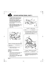
23. Install the CMCAC inlet tube and hoses
between the turbocharger and the cooler.
24. Place the coolant overflow tank in position
and install the retaining clamps.
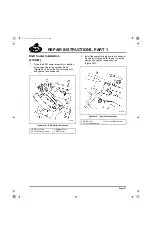
25. Install the lower radiator hose and tube.
Connect the tube to the Y-hose at the
coolant inlet of the oil cooler assembly.
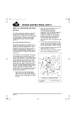
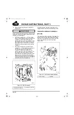
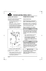
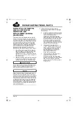
26. Reconnect the cab heater and fuel heater
coolant return lines to the radiator lower tube
(if applicable). The cab heater and optional
fuel heater coolant return hoses were
relocated from the thermostat housing to the
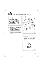
radiator lower tube during mid-2004.
446
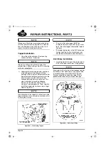
Figure 446 — Radiator Lower Tube with Welded Bosses
(Spuds) for Heater Hose Connections (CH Lower Tube
Shown)
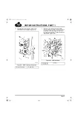
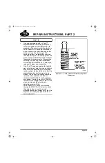
27. Install upper radiator tube and hoses. The
connection is made at the coolant outlet
fitting on the thermostat housing.
28. If the vehicle is equipped with air
conditioning:
a.
Connect the A/C refrigerant
low-pressure cutout switch to the wiring
harness connector.
b.
Connect the binary (cycling clutch)
pressure switch on the receiver/dryer to
the wiring harness connector.
c.
Connect the A/C line at the
receiver/dryer.
d.
Connect the A/C compressor discharge
hose to the system at the connection
point near the radiator support.
e.
Recharge the A/C system with
refrigerant using the refrigerant
recovery and recycling equipment,
J 39500-B, or equivalent for R134A.
29. Place the air intake tube in position and
tighten the clamps securing the intake tube
to the turbocharger and air filter.
30. Install the hood, if applicable. Refer to the
Hood Installation procedures in the
appropriate vehicle manual.
1. Fuel Heater Coolant
Return
2. Cab/Sleeper Heater
Coolant Return
3. Transmission Oil Cooler
(If Equipped)
4. Draincock
5-111.bk Page 369 Monday, July 10, 2006 2:26 PM
Summary of Contents for ASET AC
Page 6: ...TABLE OF CONTENTS Page iii TABLE OF CONTENTS 5 111 bk Page iii Monday July 10 2006 2 26 PM...
Page 14: ...INTRODUCTION Page 1 INTRODUCTION 5 111 bk Page 1 Monday July 10 2006 2 26 PM...
Page 23: ...Page 10 NOTES 5 111 bk Page 10 Monday July 10 2006 2 26 PM...
Page 96: ...COMPONENT LOCATOR Page 83 COMPONENT LOCATOR 5 111 bk Page 83 Monday July 10 2006 2 26 PM...
Page 99: ...Page 86 NOTES 5 111 bk Page 86 Monday July 10 2006 2 26 PM...
Page 100: ...TROUBLESHOOTING Page 87 TROUBLESHOOTING 5 111 bk Page 87 Monday July 10 2006 2 26 PM...
Page 140: ...MAINTENANCE Page 127 MAINTENANCE 5 111 bk Page 127 Monday July 10 2006 2 26 PM...
Page 153: ...Page 140 NOTES 5 111 bk Page 140 Monday July 10 2006 2 26 PM...
Page 383: ...Page 370 NOTES 5 111 bk Page 370 Monday July 10 2006 2 26 PM...
Page 479: ...Page 466 NOTES 5 111 bk Page 466 Monday July 10 2006 2 26 PM...
Page 480: ...SPECIFICATIONS Page 467 SPECIFICATIONS 5 111 bk Page 467 Monday July 10 2006 2 26 PM...
Page 505: ...Page 492 NOTES 5 111 bk Page 492 Monday July 10 2006 2 26 PM...
Page 513: ...Page 500 NOTES 5 111 bk Page 500 Monday July 10 2006 2 26 PM...
Page 519: ...Page 506 NOTES 5 111 bk Page 506 Monday July 10 2006 2 26 PM...
Page 520: ...APPENDIX Page 507 APPENDIX 5 111 bk Page 507 Monday July 10 2006 2 26 PM...
Page 528: ...INDEX Page 515 INDEX Index fm Page 515 Monday July 10 2006 2 48 PM...
Page 535: ...Page 522 NOTES Index fm Page 522 Monday July 10 2006 2 48 PM...