Page 262
REPAIR INSTRUCTIONS, PART 1
290
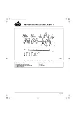
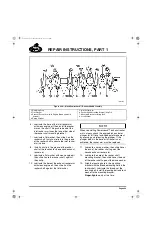
Figure 290 — Rocker Arms
Rocker Arm Adjusting Screws
앫
The pressure oil fed adjusting screws are
Armolloy coated for resistance to galling and
wear
Pinless Valve Yoke
앫
The top inboard corner of yoke has been
chamfered at a 45-degree angle, necessary
to ensure clearance between yoke tip and
the heavier rocker arm casting.
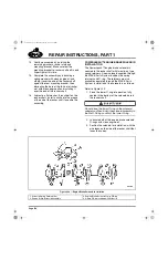
291
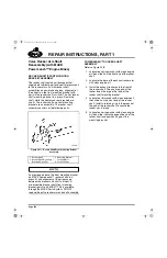
Figure 291 — Pinless Valve Yoke
The revised rocker arm components described
above cannot be intermixed with previous version
components.
With the heavier rocker arms, it is mandatory to
use the pinless valve yoke having the chamfered
tip at the top of the inboard end.
Valve Rocker Arm Shaft
Disassembly (with/without Engine
Brake)
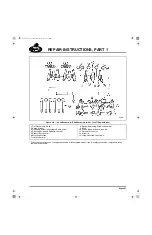
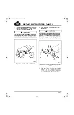
Refer to Figure 295, Figure 296 and Figure 298.
The shaft assembly is disassembled as follows:
1. If equipped with MACK PowerLeash™
engine brake, remove the solenoid from the
shaft.
2. Remove the C-clip and flat washer from one
end of the shaft.
3. Remove the outer rocker arm and spring
washer.
4. Press the mounting bracket from the shaft.
Use care not to drop the assembly as the
bracket is removed.
5. Remove the second spring washer, rocker
arm, flat washer and C-clip.
6. Repeat steps 2 through 5 to remove the two
remaining rocker arm sets from the shaft.
7. Remove the adjusting screws and jam nuts
from the rocker arms.
Changes to the rocker arm since January 2003
are significant; therefore, no components from
the current rocker arm shafts can be
interchanged with the non-current components.
1. Wider Casting at Nut
Flange
2. Revised Oil Passage
3. Near-Full Width Casting
4. Steel Bushing
1. Heavier Rocker Arm
Casting
2. Yoke with Chamfered Tip
5-111.bk Page 262 Monday, July 10, 2006 2:26 PM
Summary of Contents for ASET AC
Page 6: ...TABLE OF CONTENTS Page iii TABLE OF CONTENTS 5 111 bk Page iii Monday July 10 2006 2 26 PM...
Page 14: ...INTRODUCTION Page 1 INTRODUCTION 5 111 bk Page 1 Monday July 10 2006 2 26 PM...
Page 23: ...Page 10 NOTES 5 111 bk Page 10 Monday July 10 2006 2 26 PM...
Page 96: ...COMPONENT LOCATOR Page 83 COMPONENT LOCATOR 5 111 bk Page 83 Monday July 10 2006 2 26 PM...
Page 99: ...Page 86 NOTES 5 111 bk Page 86 Monday July 10 2006 2 26 PM...
Page 100: ...TROUBLESHOOTING Page 87 TROUBLESHOOTING 5 111 bk Page 87 Monday July 10 2006 2 26 PM...
Page 140: ...MAINTENANCE Page 127 MAINTENANCE 5 111 bk Page 127 Monday July 10 2006 2 26 PM...
Page 153: ...Page 140 NOTES 5 111 bk Page 140 Monday July 10 2006 2 26 PM...
Page 383: ...Page 370 NOTES 5 111 bk Page 370 Monday July 10 2006 2 26 PM...
Page 479: ...Page 466 NOTES 5 111 bk Page 466 Monday July 10 2006 2 26 PM...
Page 480: ...SPECIFICATIONS Page 467 SPECIFICATIONS 5 111 bk Page 467 Monday July 10 2006 2 26 PM...
Page 505: ...Page 492 NOTES 5 111 bk Page 492 Monday July 10 2006 2 26 PM...
Page 513: ...Page 500 NOTES 5 111 bk Page 500 Monday July 10 2006 2 26 PM...
Page 519: ...Page 506 NOTES 5 111 bk Page 506 Monday July 10 2006 2 26 PM...
Page 520: ...APPENDIX Page 507 APPENDIX 5 111 bk Page 507 Monday July 10 2006 2 26 PM...
Page 528: ...INDEX Page 515 INDEX Index fm Page 515 Monday July 10 2006 2 48 PM...
Page 535: ...Page 522 NOTES Index fm Page 522 Monday July 10 2006 2 48 PM...


