


REPAIR INSTRUCTIONS, PART 1
Page 309
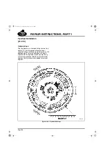
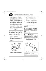
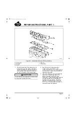
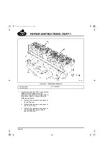
2. Align the timing marks. First look at the
timing marks on both the camshaft and
crankshaft gears. Note that two teeth are
marked (side-by-side) on each gear. These
double timing marks must align with the
single timing marks on the idler gear. When
properly installed, the two single timing
marks on the idler gear will fall between the
double timing marks on the camshaft and
crankshaft gears. To attain correct
alignment, rotate the crankshaft and
camshaft gears until the camshaft timing
marks are in approximately the 3:30
position, and the crankshaft gear timing
marks are in approximately the 1 o’clock
position (with engine in the upright position
and viewed from the front).
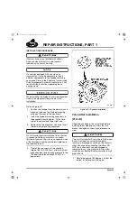
There are 45 gear teeth on the crankshaft gear,
90 teeth on the camshaft gear and 48 on the idler
gear. Because the idler gear has 3 more teeth
than the crankshaft gear, the timing marks align
only once every 16 revolutions of the crankshaft.
This is called a “hunting tooth” system.
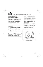
3. Slide the idler gear onto the hub assembly
with timing marks facing out.
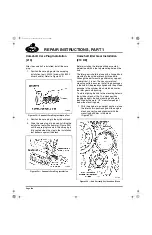
4. Position the idler gear timing marks so they
align (Figure 355) with the crankshaft and
camshaft gear timing marks. Then, slide the
idler gear/hub assembly into position on the
cylinder block.
355
Figure 355 — Timing Marks Properly Aligned
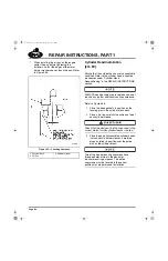
5. Coat the hub bolts with clean engine oil and
thread the bolts a few turns into the
respective bolt holes at the front of the
engine block.
6. Tap the hub portion of the assembly with a
brass hammer to seat the components.
7. Tighten the bolts evenly to specification,
70 lb-ft (95 N
폷
m). Do not use an impact
wrench or other air tool to tighten bolts.
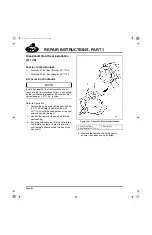
Auxiliary Shaft Installation
[212 CV]
Before installing the auxiliary shaft in the engine,
ensure that the shaft is clean, undamaged and
well-lubricated with clean engine oil. Refer to
“Auxiliary Shaft and Camshaft Bench
Procedures” in the REPAIR INSTRUCTIONS
section.
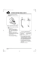
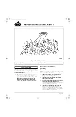
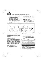
Refer to Figure 356.
Replace the auxiliary shaft as an assembly only.
Do not try to dismantle or rework the shaft since
doing so may result in damage to the engine.
1. Lubricate the front auxiliary shaft journal,
rear auxiliary shaft journal and shaft
bearings (in cylinder block) with clean
engine oil.
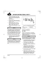
356
Figure 356 — Auxiliary Shaft Installation
1. Rear Bearing
2. Auxiliary Shaft Front
Journal
3. Shaft
4. Auxiliary Shaft Rear
Journal
5. Oil Pump Drive Gear
5-111.bk Page 309 Monday, July 10, 2006 2:26 PM
Summary of Contents for ASET AC
Page 6: ...TABLE OF CONTENTS Page iii TABLE OF CONTENTS 5 111 bk Page iii Monday July 10 2006 2 26 PM...
Page 14: ...INTRODUCTION Page 1 INTRODUCTION 5 111 bk Page 1 Monday July 10 2006 2 26 PM...
Page 23: ...Page 10 NOTES 5 111 bk Page 10 Monday July 10 2006 2 26 PM...
Page 96: ...COMPONENT LOCATOR Page 83 COMPONENT LOCATOR 5 111 bk Page 83 Monday July 10 2006 2 26 PM...
Page 99: ...Page 86 NOTES 5 111 bk Page 86 Monday July 10 2006 2 26 PM...
Page 100: ...TROUBLESHOOTING Page 87 TROUBLESHOOTING 5 111 bk Page 87 Monday July 10 2006 2 26 PM...
Page 140: ...MAINTENANCE Page 127 MAINTENANCE 5 111 bk Page 127 Monday July 10 2006 2 26 PM...
Page 153: ...Page 140 NOTES 5 111 bk Page 140 Monday July 10 2006 2 26 PM...
Page 383: ...Page 370 NOTES 5 111 bk Page 370 Monday July 10 2006 2 26 PM...
Page 479: ...Page 466 NOTES 5 111 bk Page 466 Monday July 10 2006 2 26 PM...
Page 480: ...SPECIFICATIONS Page 467 SPECIFICATIONS 5 111 bk Page 467 Monday July 10 2006 2 26 PM...
Page 505: ...Page 492 NOTES 5 111 bk Page 492 Monday July 10 2006 2 26 PM...
Page 513: ...Page 500 NOTES 5 111 bk Page 500 Monday July 10 2006 2 26 PM...
Page 519: ...Page 506 NOTES 5 111 bk Page 506 Monday July 10 2006 2 26 PM...
Page 520: ...APPENDIX Page 507 APPENDIX 5 111 bk Page 507 Monday July 10 2006 2 26 PM...
Page 528: ...INDEX Page 515 INDEX Index fm Page 515 Monday July 10 2006 2 48 PM...
Page 535: ...Page 522 NOTES Index fm Page 522 Monday July 10 2006 2 48 PM...