


REPAIR INSTRUCTIONS, PART 1
Page 305
INSTALLATION PROCEDURE
After resurfacing, any flywheel with drilled
balance holes on the clutch side requires
rebalancing by a machine shop.
On vehicles equipped with an automatic
transmission, it may be necessary to install
different components to the flywheel retaining
capscrews. Refer to the Automatic Transmission
Drive Arrangement Assembly Instructions, 5-902,
for installation instructions regarding these
arrangements.
When installing the flywheel, insert two alignment
studs in the crankshaft flange to aid in the
installation.
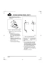
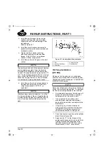
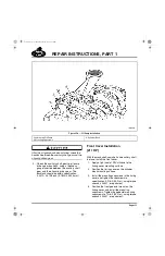
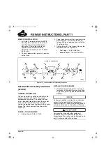
Refer to Figure 347.
1. Position the flywheel over the dowel pin and
alignment studs on the flywheel mounting
surface at the rear of the crankshaft.
2. Install the flywheel mounting capscrews in
the exposed mounting holes. At this time,
tighten the capscrews finger-tight only.
3. Remove the two alignment studs and insert
the remaining mounting capscrews.
Do not torque capscrews adjacent to each other
in sequence. Doing so may result in uneven
flywheel alignment. Capscrews on opposite sides
of the flywheel should be alternately tightened to
the specified torque.
4. Tighten the capscrews to the specified
torque, 185 lb-ft (250 N
폷
m), alternating from
opposite sides to apply even pressure to the
flywheel (use torque wrench J 24407, or
equivalent).
347
Figure 347 — Flywheel Installation
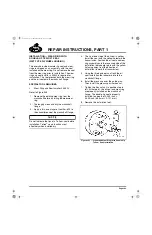
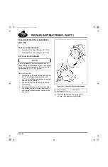
Valve Lifter Installation
[213 LB]
Check the condition of the valve lifters before
installing them. Replace any lifters that are
broken, damaged or show signs of excessive
wear.
Ceramic lifter rollers will not tolerate high impact
loads. Such loads can crack the ceramic,
resulting in breakage or spalling of the ceramic
roller. Use care when handling the lifters. DO
NOT use a lifter that has been dropped or
subjected to any type of engine failure which
would have subjected the ceramic roller to high
impact loads.
1. Rotate the engine 180 degrees, so that the
bottom of the engine is facing up.
5-111.bk Page 305 Monday, July 10, 2006 2:26 PM
Summary of Contents for ASET AC
Page 6: ...TABLE OF CONTENTS Page iii TABLE OF CONTENTS 5 111 bk Page iii Monday July 10 2006 2 26 PM...
Page 14: ...INTRODUCTION Page 1 INTRODUCTION 5 111 bk Page 1 Monday July 10 2006 2 26 PM...
Page 23: ...Page 10 NOTES 5 111 bk Page 10 Monday July 10 2006 2 26 PM...
Page 96: ...COMPONENT LOCATOR Page 83 COMPONENT LOCATOR 5 111 bk Page 83 Monday July 10 2006 2 26 PM...
Page 99: ...Page 86 NOTES 5 111 bk Page 86 Monday July 10 2006 2 26 PM...
Page 100: ...TROUBLESHOOTING Page 87 TROUBLESHOOTING 5 111 bk Page 87 Monday July 10 2006 2 26 PM...
Page 140: ...MAINTENANCE Page 127 MAINTENANCE 5 111 bk Page 127 Monday July 10 2006 2 26 PM...
Page 153: ...Page 140 NOTES 5 111 bk Page 140 Monday July 10 2006 2 26 PM...
Page 383: ...Page 370 NOTES 5 111 bk Page 370 Monday July 10 2006 2 26 PM...
Page 479: ...Page 466 NOTES 5 111 bk Page 466 Monday July 10 2006 2 26 PM...
Page 480: ...SPECIFICATIONS Page 467 SPECIFICATIONS 5 111 bk Page 467 Monday July 10 2006 2 26 PM...
Page 505: ...Page 492 NOTES 5 111 bk Page 492 Monday July 10 2006 2 26 PM...
Page 513: ...Page 500 NOTES 5 111 bk Page 500 Monday July 10 2006 2 26 PM...
Page 519: ...Page 506 NOTES 5 111 bk Page 506 Monday July 10 2006 2 26 PM...
Page 520: ...APPENDIX Page 507 APPENDIX 5 111 bk Page 507 Monday July 10 2006 2 26 PM...
Page 528: ...INDEX Page 515 INDEX Index fm Page 515 Monday July 10 2006 2 48 PM...
Page 535: ...Page 522 NOTES Index fm Page 522 Monday July 10 2006 2 48 PM...