MM102225V1, Rev. B
13
2.0 SITE
PREPARATION
2.1 INTRODUCTION
This section provides instructions for preparing the site and other installation items,
which must be completed prior to installing OpenSky Communication equipment. The
areas covered include the following:
Antenna System
- This includes installation of the antenna tower, receive and transmit
antennas, tower top amplifier and the installation of the transmission lines from the
antenna to the tower top amplifier to the equipment shelter.
Site Requirements
- Information is provided concerning various factors, which may
affect the physical location of the equipment facility.
Facility Preparation
- This section provides information for preparing the facility prior
to installing the equipment. This information includes proposed equipment layout,
environment, electrical power, equipment room grounding and telephone line installation.
2.2 ANTENNA
SYSTEM
This section covers installation of the antenna system, including RF cables from the
antennas to the equipment room wall feedthrough.
Antenna systems are generally installed by crews trained and equipped for working on
antenna towers. As a result, this manual assumes the Antenna systems are installed by
crews with the specialized equipment and skills required for working on towers and
installing the antenna cables. However, it may be necessary for the system installer to
provide information and directions to the crew installing the antenna system and to verify
proper installation.
2.2.1
Antenna Mounting
The antenna tower must allow antenna mounting that provides isolation of at least 25 dB
between the TX and RX antennas. This is necessary to avoid interference in the trunked
receivers caused by the trunked transmitters. An isolation of greater than 25 dB is easily
obtained by placing one antenna directly above the other on the tower (minimum 10-foot
separation).
2.2.2
Transmission Lines
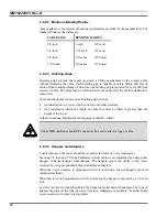
When installing the transmissions lines, refer to the diagrams contained in Antenna
System Maintenance Manual LBI-38983.
2.2.2.1 Length
The length of the main coaxial cable for each antenna is planned as a continuous run with
no connectors or splices between the antenna and the equipment room. Each cable
includes a 50-foot allowance for the distance from the bottom of the tower to the
equipment room. Smaller diameter, more flexible coaxial cables are used at both ends of
the main coaxial cable to facilitate installation.
Summary of Contents for P5100 Series
Page 2: ...Installation Manual MM102225V1 Rev B Jul 05 Base Station Tower Site ...
Page 70: ...MM102225V1 Rev B 69 This page intentionally left blank ...
Page 72: ...MM102225V1 Rev B 71 This page intentionally left blank ...
Page 74: ...MM102225V1 Rev B 73 This page intentionally left blank ...
Page 76: ...MM102225V1 Rev B 75 This page intentionally left blank ...
Page 82: ...MM102225V1 Rev B 81 PARAMETER VALUE EXPLANATION password cisco login end buck40sas ...
Page 92: ...MM102225V1 Rev B 91 This page intentionally left blank ...
Page 94: ...MM102225V1 Rev B 93 This page intentionally left blank ...
Page 96: ...MM102225V1 Rev B 95 This page intentionally left blank ...
Page 99: ...MM102225V1 Rev B 98 This page intentionally left blank ...


