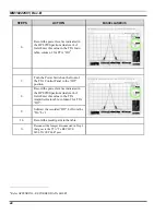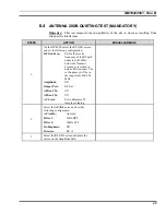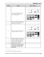
MM102225V1, Rev. B
50
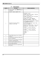
STEPS
ACTION
MISCELLANEOUS
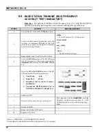
4.
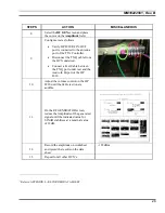
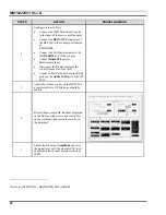
Configure test as follows:
•
Connect the 30dB Directional Coupler
to the input of the receive multicoupler.
•
Connect the
RF IN/OUT
connector of
the HP 8920 to the coupler port labeled
as
TO ANALY
.
•
Connect the 50-Ohm terminator to the
ANT/TERM
port of the coupler.
•
Connect
Duplx/SPL
port to
Multicoupler Input.
•
Disconnect the
Tx Q
cable from the
controller module of the DCX.
•
Connect a Test Cable between the
Tx Q
port and the
Audio In Hi
port of the HP
8920.
5.
Adjust the volume control on the HP 8920 to
a comfortable level. White noise should be
audible.
6.
Record the measured
AC Level
as displayed
on the RF Generator screen and record this
on the worksheet and record the results on
the datasheet
9
.
7.
Enable the RF output
Amplitude
and raise
the signal level until the measured AC level
of demodulated channel noise decreases by
20dB.
9
Refer to APPENDIX L - RECORDED DATA SHEET
Summary of Contents for P5100 Series
Page 2: ...Installation Manual MM102225V1 Rev B Jul 05 Base Station Tower Site ...
Page 70: ...MM102225V1 Rev B 69 This page intentionally left blank ...
Page 72: ...MM102225V1 Rev B 71 This page intentionally left blank ...
Page 74: ...MM102225V1 Rev B 73 This page intentionally left blank ...
Page 76: ...MM102225V1 Rev B 75 This page intentionally left blank ...
Page 82: ...MM102225V1 Rev B 81 PARAMETER VALUE EXPLANATION password cisco login end buck40sas ...
Page 92: ...MM102225V1 Rev B 91 This page intentionally left blank ...
Page 94: ...MM102225V1 Rev B 93 This page intentionally left blank ...
Page 96: ...MM102225V1 Rev B 95 This page intentionally left blank ...
Page 99: ...MM102225V1 Rev B 98 This page intentionally left blank ...

